Now for something totally different !!.
I have a pair of dogs. Recently, while he was out running loose, the elder one managed to lose his collar.
Since the pup was also outgrowing her puppy collar I decided it was time she moved on to her adult collar and to make up a pair of matching collars for them.
So I went to the local suppliers, LePrevo Leather <http://www.leprevo.co.uk/>, and bought one 2 inch and two ¾ inch straps of a good leather along with four ¾ inch brass “D” rings, two 1 inch brass “O” rings, some copper rivets and two brass trigger hooks.
Once I had the materials next thing was to measure up. What I intended to make was a pair of martingale collars and for these I needed an accurate measure of the dogs neck size, his lordship measured up as being 16½ inches and her ladyship was 14 inches.
Allowing for the size of the “D” rings this meant that his collar leather needed to be a 14 incher while hers was to be 12 inches to allow her room to “grow into it”.
The dogs are a pair of standard poodles, poodles are a long-necked dog and as such I prefer them to wear a broad “fishtail” type collar so next step was to mark out the 2 inch strap for this and cut it to the required shape.
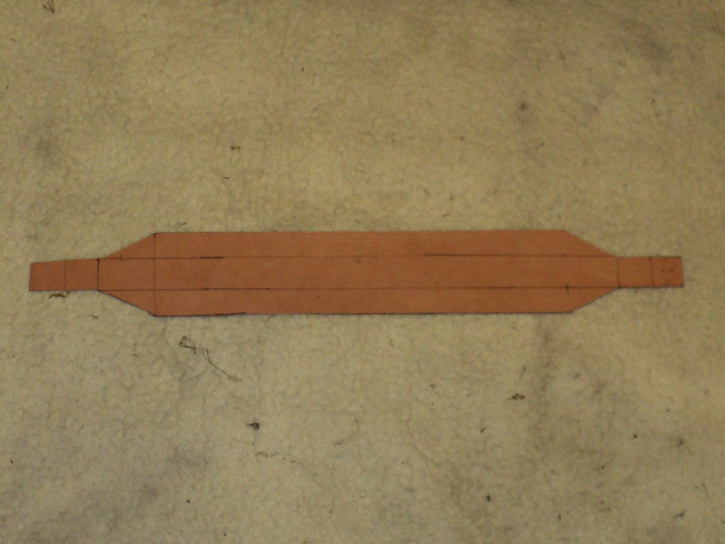
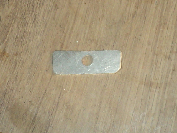
Cutting Template
A cutting template was made from some stiff card and transferred to the leather, which was then cut to shape using a Stanley knife fitted with a new blade.
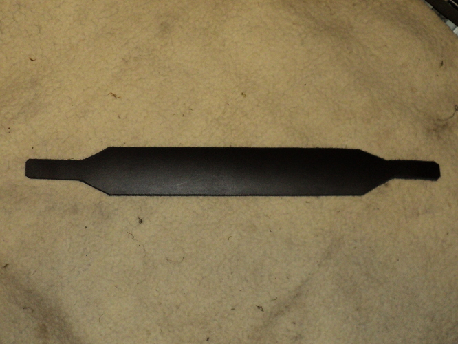
Leather Main Body
Next a “D” ring was slipped over one of the “tails” and the “tail” doubled over it. This now needed to be fixed in place and there are two options here, you can stitch it in place or you can rivet it place, as these collars are for a larger dog and have ¾ inch wide “tails” stitching is a better option, for a small dog, and so a narrower collar, using ½ inch “D” rings then in preference I’d rivet it.
Leather is not as easy to sew as fabric is and it needs to have the needle holes pre-punched, you can’t just push a needle through two thicknesses of leather. What is needed here is a “pricking iron”, this looks a bit like a fork and is used to mark out and pre-punch the leather.
Once the thread holes have been pre-punched then it’s just a case of using an awl to open and line up the holes’ and then running the needle through.
When sewing leather it is normally done using two needles, one on each end of the thread, so you then run the other needle back through the other way and pull the thread tight and that’s the first stitch made.
Then you just run the awl through the next holes, follow it with the needles and so on till that stitch row is completed.
For security a second row of stitches was run across the “tail”, a bit nearer to the “D” ring.
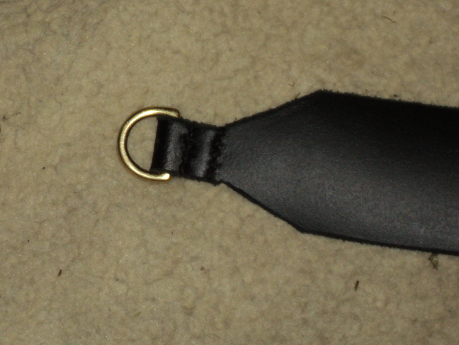
“D” Ring Stitched in Place
That meant the first “D” ring was now in place and all I had to do was stitch up the other three and I had the collar main bodies finished.
The bigger collar was 14 inches long and the smaller was 12 inches and the strap was 46 inches long so I had 20 inches of the strap “spare”
This “spare length” was cut down so as to give two straps, each ¾ inch wide by 20 inches long and one of these was slipped through both “D” rings on one collar.
As this loop was to be riveted closed, a small hole was punched through the strap length, about a ½ inch from either end and another hole a bit over 1¼ inches from one end.
The strap was now slipped through one of the 1 inch “O” rings, the strap end doubled over the ring. A rivet was then put through all three holes and “set up” to secure it in place.
All that was now left to do was to make up a slider to go over the strap loop and secure it.
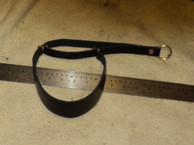
Completed Martingale
For this a short length of the “spare” leather was doubled over the loop and the ends riveted in place so that it would slide stiffly over the loop and that was that collar completed,
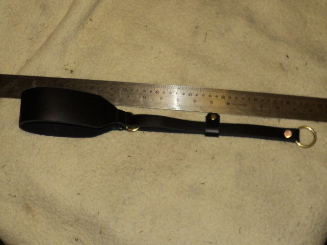
Slider Fitted to Martingale
all that was now left to do was to finish her ladyships collar as well.
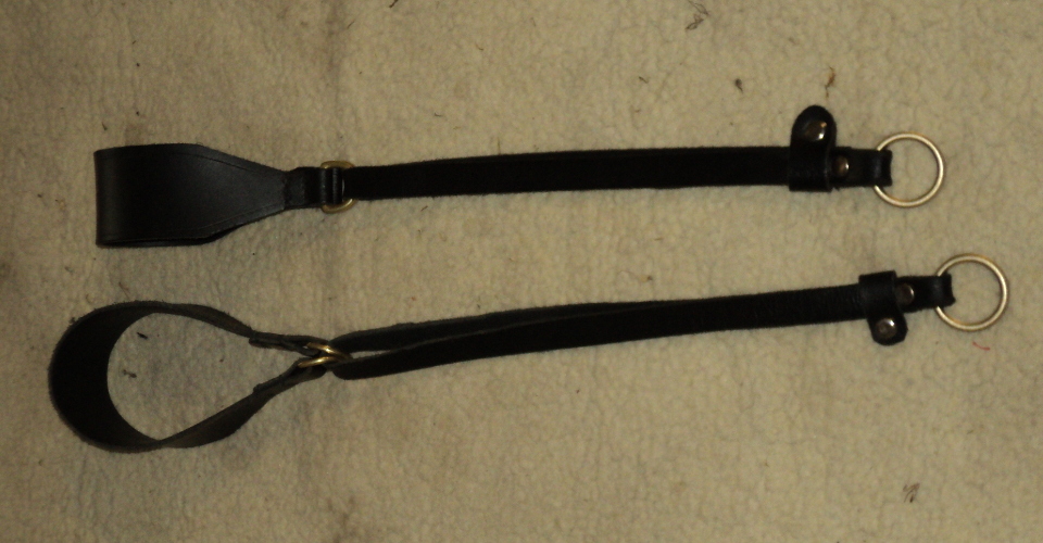
Completed Pair of Martingales
To complete the “sets” I needed leaders to go with the collars.
For these I had the two strap lengths of ¾ inch wide leather.
I just slipped one end through the loop on one of the trigger hooks, doubled it back on itself and stitched the loop closed. As with the “D” rings I used two rows of stitching to secure it.
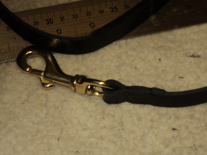
Trigger Hook stitched onto Leader
To form the handle I doubled the opposite 9 inches of the strap back on itself and secured it in place with another two rows of stitching and that was the leader complete.
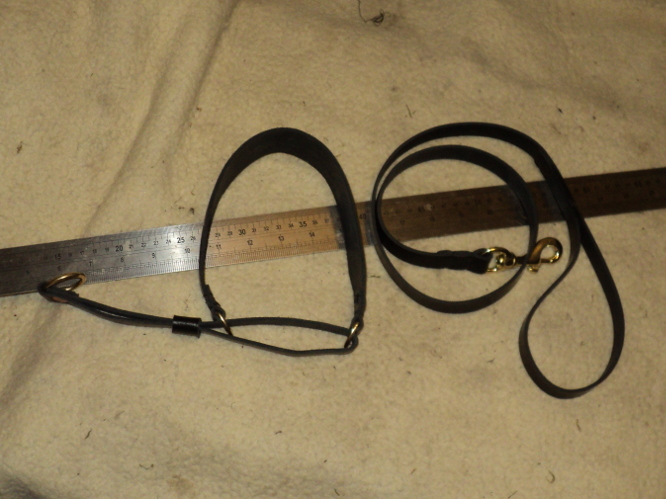
Set of Martingale and Leader
The idea of these “martingale” collars is that if the dog pulls hard when walking on lead then the collar is pulled a bit tighter round his neck, but, because from the way it is made it can only “pinch down” by about 1 inch on a 16 inch collar so it is uncomfortable to the dog rather than choking it.
It is not meant to be worn continually, it should be kept along with its leader as a set, the pair being put on when the dog is taken out and then removed, as a pair, when you get back home.
As long as the slider is run up to near the “D” rings the dog can be allowed to run loose “off lead” while wearing it since the slider holding the loop closed means the dog cannot get his foot caught in the open loop.