Monthly Archives: March 2013

Getting to Grips.

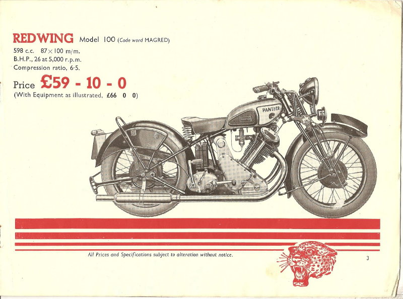
One thing that’s missing is the mounting-plates for the knee-grips on the tank.

When I got this bike there was only one knee-grip fitted and this was the wrong type, it was the later type that mounts through holes in the grip itself and it was looking rather sad for itself as well.

Back when I first got this bike the P&M spares shop was still open on a Wednesday and as I was in the vicinity of Cleckheaton one Wednesday I went in.

Talk about going back in time, anything with a price tag on it was still marked up in £.s.d., none of this new-fangled decimal currency!, parts for pre-war models lying next to Model 120 stuff, a cylinder head priced at £6:5:0, (For those who can’t remember that’s £6:25), wish I could get back there now!.

Anyway I came away with a set of new knee-grips, some valve guides, a set of the top engine mount spacer-bushes and some transfers and I don’t remember being it over a fiver, I don’t think the prices had changed since the Fifties!.

They had the transfers in a box, there were tank transfers going back to the First War “RAF” models and I was told to take what I wanted, I only took the ones for my bike but could have taken a bigger selection and wish I had now, they’d be ideal for samples for the transfer scheme.

Typically, even though I needed the mounting-plates for the knee-grips I forgot to ask if they had any, and they’re hardly an over the counter spare in the bike shops today!.

So, I got a drawing of the plate through the Panther Owners Club, went down to Metals Supermarket, got some sheet steel and set to.
Drawing of knee-grip plate

This is what I needed (Drawing courtesyof P.O.C.)
I got two pieces of 16 gauge steel, each 4 inches by 8 inches and I marked one plate out from the drawing. These plates bolt onto the tank so there are two 5/16 inch slots in them for this purpose.

I drilled a 6mm hole at one end of each slot and then used these to bolt the two plate together.
Rough cut

This is the result of attacking the plates with a Hacksaw
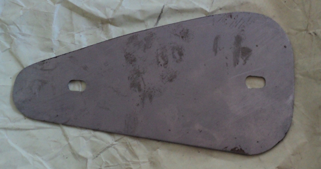
Using a hacksaw I then roughed out the two plates to an approximation of the correct shape and then it was down to use of a file to shape them down to the marked outline.
Filed down

3/4 of an hour with files gave this result
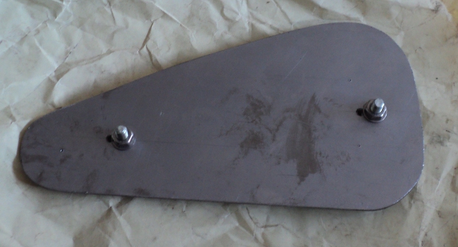
As the mounting slots are 9/16 inch long the next thing was to drill the holes for the other ends of the slots, I’d already drilled a pilot hole for these when I drilled the 6mm holes.

This left a thin web between the holes so it was just cut this web, finish off the slots with a file and it was job done all bar the painting!
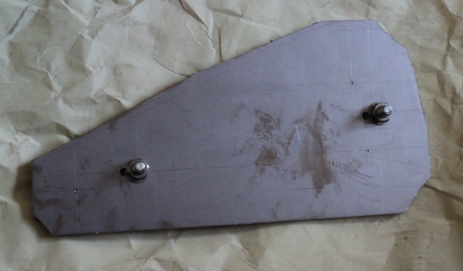
DSC0669

Ready to paint

I’ve tried the plates in the knee-grips and they fit as they should, I can see it being a fiddle to fit them once the plates are bolted to the tank.

Trying them on the tank shows that they will need to be bent into a curve to match the shape of the tank, so that’s going to be a job with a sand bag and a rubber hammer.

Instruments

It is a legal requirement that any vehicle of over 100cc engine capacity, first registered after September 1937 must be fitted with a speedometer.

My old girl was registered on 1st of January 1938 and so she must have one fitted and of course there had to be one fitted as standard equipment when she was first used, it was an 80 mph Smiths/Jaeger type chronometric instrument.

Most UK vehicles at this time used speedometers built by Smiths, who had taken over the French company, Jaeger, and were using their designs.

The instruments were marked on their faces as being of Smiths/Jaeger mamnufacture up until about 1939 and that was also when they changed the drive input design to the modern squared end on the drive cable.

Among the stuff with my bike there were two speedo heads, one a Jaeger type and the other a later Smiths but both needing attention.

I knew the Smiths head worked as I had used it previously but it did need refurbished, and the servicing of these chronometric type instruments is not for the home mechanic!.

So it was onto the ‘net and into the magazines to find someone who did this type of work and I decided to try “Chronometric Instrument Services” in Nottingham. I contacted them by e-mail and received a reply within two hours.

I then ‘phoned them, we discussed the job and he made what struck me as a very fair offer for a full restoration of the Jaeger, especially as it was a firm price, sight unseen of the job with just my description of it, which I was as accurate with as I could be as a layman.

So I packed it up and sent it down on Monday March 4th. I received a ‘phone call on Friday 22nd March to say that it was ready.

It arrived in todays post, Tuesday 25th March, and it was difficult to believe it was the same instrument, it was better than new!, Good enough to put on show on the mantelpiece rather than putting it on the bike.

DSC0658      DSC0652

This is the speedo head as it was sent down to Chronometric Instruments Services, looking rather sorry for itself, and No!, I did not fit that needle to it.

DSC0664      DSC0665

and this is how it came back, doesn’t look like it’s the same instrument does it ?. The drive goes onto that stub shaft off to one side on the back, the speedo cable has a cup on the end that it fits into and there is a set screw locks them together.

The only other instrument on the bike is the ammeter.

These used to be a standard fitting on both cars and bikes so you could keep an eye on your battery charging. All they really showed was whether the battery was being charged by the dynamo or the battery was discharging to feed the lights.

The Panther uses a Miller electrical system so the ammeter should be a Miller instrument.

Fortunately the correct one is fitted in the headlamp, a 2 inch diameter white-face unit.

It’s the pukka pre-war unit as well. Most of the post-war instruments were smaller diameter and the text on the face was different, only thing was “Does it work?” so I tried it with an old AA dry battery and it swung over both ways according to how I connected the battery so it looks like I’m lucky there.


Lights.

The headlight for this bike is an 8-inch Miller unit.

I do have a good headlamp shell for her but it was fitted with a 7-inch Lucas light unit in a modified Lucas 8-inch to 7-inch reducer rim, not only that but that rim is badly scarred.

While it would be a simple job to knock out the dent caused by the scarring, getting it polished out well enough not to show on the rechromed rim is another matter so it was on the search for parts.

Checked the usual sources, Feked, Burton, Armour, Goffy, VWP and such and while I could readily get an 8-inch Miller lens/reflector unit, the only 8-inch rims I could find were for Lucas headlights.

Miller and Lucas of course use different and non-compatible methods to fit the rim onto the headlamp shell. One of these sites also had a note that the rim was only suitable for a flat glass light unit, the available Miller light units being, of course, domed glass.

Sudden idea!  Velocettes used to use Miller electrics! so I went looking for a Velo parts site and found Grove Classic Motorcycles.

They are a Velo specialist, but of course there is always a range of “Universal” parts so it was onto their web-site.Once there I went straight to the “Electrics” section and sure enough there was an 8-inch Miller lens/reflector there. At first sight though I could only see a Lucas 8-inch rim to go with it.

However on a general trawl through the site for whatever else they had that might be useful I found, under “Miscellaneous”, a choice of not only  an 8-inch Miller rim for a flat glass along with a Miller flat-glass/reflector unit to suit, but an 8-inch rim for the domed glass/reflector unit as well and not only that but they had a handlebar switch I was looking for to suit the 1-inch handlebar my old lady uses.

So it was out with the card and order up the bits. I ordered them yesterday (Thursday) morning and they arrived this morning, (Friday), you can’t ask for better than that!.

Only found two downsides, one was that I had to fit the toggle clip to the rim because it is supplied as a separate unit. This was only a minor hassle but of course has the advantage that in the event of damage to the toggle it does not mean a complete new rim and the other was that when I went to fit the lens unit into the rim and I found that I only had one suitable “W”-clip, the ones in the old unit were too long!, I should have thought of that of course and the ones from the old 5-inch headlamp in the shed were too short, a typical appearance of “Sods Law”!.

Anyway, I’ve got a set of “W”-clips now and have the headlamp together as a unit, looks well. Now I’ll have to see about making up a set of headlamp stays, one thing leads to another all the time.

Tank Attack, First Phase

As the weather is currently on the damp side, I’ve taken the opportunity to step away from the work plan and finish prep the tank.

I’ve spent an industrious morning rubbing it down ready for the finishing coats.

In case you’ve never done a prep yourself here’s a run through.

First the tank was cleaned to bare metal and treated with an acid etch primer to kill off any rust remaining in the nooks and crannies, this left it with a red “base colour”.

Next a coat of grey primer filler was applied and allowed to dry, this was followed by a coat of beige primer filler, then another of grey and another of beige.

By this time the surface pitting had disappeared and it looked level so it got another coat of grey.

I now had 5 layers of primer of contrasting colours on top of the red base coat.

I had a spray can of black left from another job so I used this to apply a light coat, little more than a dusting on top of the whole, this is the “witness coat” and it does not matter what colour it is. The tank was then put to one side to “cure out” and let the paint solvents evaporate.

This was done a couple of weeks ago so this morning it was out with the “Wet and Dry”  carborundum paper and set too.

I used two pieces of  400 grade wrapped over a stiff sponge block and started with that, using it wet.

First thing was to reduce the “new cut”of the paper so the two pieces were put face to face and given a quick rub against each other.

Toss one piece into a bucket of water with a shot of washing up liquid added and then start rubbing down with the other wrapped round the sponge, change the pieces frequently so they do not become clogged.

Idea is that you have one in use and one in soak and every now and then you wipe the job surface clean with another, softer, sponge

The aim is to rub off the “witness coat” without going through to the base coat.

As you go on you quickly see that what appeared a smooth surface was not as the witness coat is rubbed off the high spots but remains in the dips.

Here’s where the advantage of the alternate colours of primer shows itself since you can keep check of how near to the base coat you are getting as you rub the high spots away.

By the time you have removed all the witness coat you have a smooth surface, ready for the finishing coats, but not yet!.

You’ve rubbed the surface down wet, primer is porous, so the tank has now been put aside to dry out again before the top coats go on.

It’s a laborious, time-consuming job and is where the big money goes in a paint job, the final finish is dependant on the quality of the prepared surface as any blemishes will show through.

The New Saddle Arrives

Well the new saddle has now arrived, it is a close copy of the original Lycett, quite nicely finished and looks the part when offered up to the bike frame.

It came with a pair of new support springs but these have only half of the number of turns of the originals and have a very “stretched out” look to them so they will not be used as they “do not look right”.

When I went to bolt on the support brackets to the saddle frame I found that the copy was not as close as it might be, since the mounting hole centres in the brackets were about 1mm closer together than those on the saddle, but a little work with a rat-tail file and all was well.

Then, once the brackets were bolted up it was obvious that they were not parallel to each other but were splayed, so I gripped them one at a time in the vice, applied a little pressure to the saddle frame to bring them into line and the new saddle is now mounted in place (well, I’ve still to bolt the support springs to it but that’s all).

With the current foul weather all I’ve got done with the paint job is  to rub down the front hub, which is now ready to receive its top coats before it goes to the wheel-builder.

I’ve also rubbed the tank down but it still needs a bit of work before it gets its top coats, there are still a couple of scars visible through the primer.

I was hoping to get away with giving it just a heavy coat  of spray-on primer/filler but it looks like I’ll need a spot of filler on the scarring, rub it down flush and then another coat of the primer and rub it down again before the topcoats go on.

For a 1937/38 bike the tank should be finished in chrome plate with cream side panels but the tank I have has suffered the ravages of the dreaded tin-worm and is corrosion pitted. By the time these pits were polished out the tank metal would be thinner than I like for a fuel tank so rather than try to re-chrome it I’m going to use the older colour scheme of a dark green tank with light green panels. I will however use the 1937 tank logo of the Panther head rather than the Leaping Panther of the earlier models.

Working on the tank has revealed another problem, the fuel tap.

This tank has only one outlet so you need a tap with a built-in reserve, the one fitted is the old flat slide “Hexag – ON” type and is beyond redemption,

Easy enough, these are still listed both with and without reserve, that is until you look closer and find that P & M, in their ineffable wisdom, have used a tank boss to take a 1/8 inch BSP tap body.

The normal taps have a 1/4 BSP body which will not fit and as it’s a smaller tank thread you cannot use an adaptor bushing!.

I’ve tracked ONE supplier who lists this tap with a reserve lever, all the others only have the 1/4inch version or the 1/8inch tap WITHOUT a reserve, and of course the 1/8inch tap is twice the price of the 1/4inch one, I’ve had to push this old lady once through running out of fuel and I’ve no intention of doing it again!, that’s how I know the current tap is buggered.

So I got onto that supplier, only to be told it was out of stock and they did not know when they’d have any more in, Typical!.

It’s beginning to look like I’ll have to modify the tank mount to take the standard tap!.

Saddling Up

As we are having a cold snap at the moment it’s too cold to think about applying paint to the hub and brake plate so I’ve turned my attention to the saddle.
I have the frame and about half the mattress springs, not only that but one of the support springs has broken.
Recalling from years ago that there was a firm called Armours down in Bournemouth who used to supply new saddle covers and such I went on-line, looked them up on Google and found that they were still trading, its got to be over 20 years since I last dealt with them so I  was a bit surprised, but anyway I downloaded their catalogue and spent the next hour or so going through it.
Having potentially spent a not so small fortune on all the “I could just do with that” items  in the catalogue I found new mattress springs listed, along with a choice of lengths of support springs and saddle covers as well as an “assembly required” reproduction saddle.
So it was on the ‘phone to place the order, only to be met with “We can do the springs but not the top. Sorry, but we no longer do those!”, I thought it was too easy to be true!.
So it was back onto the ‘net again and I found a “copy of the large Lycette’s saddle” on a web site in India, a bit more digging and I found a UK site, “Burton Bike Bits”, that not only listed this saddle but had a couple of photographs of it posted, it looked right.
I dropped them an e-mail asking for dimensions and had a reply inside 2 hours answering my query and confirming that it was indeed a close replica of the original and at a cost of £35, that’s less than I was expecting for a cover and replacement set of springs, so it was promptly put on order!.

A problem coming up is that the thread form used throughtout the bike is the old CEI system, which is long obsolete.

This uses the old Whitworth/BSF spanner sizes and like them is sized on the bolt diameter rather than the across flats spanner size but unlike those it uses a standard 26 threads per inch pitch across the board and a 60degree thread angle.
As many of the existing threads on the bike are going to be bruised and/or corroded they’ll need to be cleaned.
I’ve already had a word with Bob the Engineer about this and he’s put me onto a trade supplier for threading tools, Tracy Tools, and sure enough they have Cycle taps and dies listed.
For £20 I can order up a set of taps for the 5 sizes between 1/4inch and 1/2 inch and another £20 will get me the matching dies. They’re in carbon steel rather than HSS but that’s alright, I’ll be using them to clean existing threads, not for cutting new ones.

Things move on.

I’ve been to see the wheel-builder with the front wheel in order that that he can get the spoking pattern and the rim offset noted down, as well as measuring the spoke lengths required.

Since the hub needs to be repainted it makes more sense to strip the wheel down myself so I’ve been down to Machine Mart, bought myself a set of 18-inch bolt croppers and cut the spokes out of the front wheel, now I’ve got to clean up the hub and paint it before I can get the wheel rebuilt.

I’ve put the new rim on order so I can get the centre rib of that painted as well, you can see the way this is to be done in the picture of the 1933 Panther at the head of this Blog.

On the trip to the wheel-builder I also went by a small engineering firm I used to use for repair-work when I was running the bike-school.

The speedometer drive is taken from the front wheel on these old ladies, this is done with a drive-box mounted onto the front brake plate, taking its drive from a gear-wheel mounted on the bearing “nose” of the front hub.

There is a mounting boss fitted onto on the brake plate to take this drive-box and the boss on the brake plate has come loose.

So I took it into the firm, (Specialist Services, to give them a plug).

The boss of the place, Bob, took a look at it, set it upon the bench there and then and TIG-welded it in place from the inside.

He’s done a beautiful job, one that will not show once the paint is on the brake-plate.

Back home and having cut the hub out of the wheel it needed to be cleaned of rust and repainted.

I put a wire brush head onto the angle grinder and tried that on the bare hub, it ate the rust!.

I found that with very little effort the wire brush stripped what was left of the old paint back down to bare metal and also removed the rust leaving a clean, burnished steel surface.

In order to stop this re-rusting immediately, and to kill any rust remaining in the bottom of the pitting, I coated it at once with Kurust and this will also give a solid base for the paint to cling onto.

I already have some high-build etching primer/filler in stock so once the Kurust has had time to cure out, “after 3 hours” according to the bottle, I’ll get a first coat of the primer onto the hub.

I’m probably going to have to compromise between getting a perfect gloss finish and not having too great a thickness of paint on the hub itself here as it will need a fair bit of the primer/filler to fill the worst of the pits up to get a perfect finish but if I have to much paint on the hub it will lift when the hub gets hot under braking, especially with a sidecar hitched to the old girl but after all the intention is to use her on the road and not to have a “show queen”.

March 9th

I’ve joined the Panther Owners Club now.

This gives me access to their library of the history of the marque, parts lists and owners manuals plus a lot of other Panther specific information which will be useful as I progress with the rebuild.

They also have a members spares scheme where many of the specialised Panther parts are available which will be very useful.

This club has a web-site up at <http://www.pantherownersclub.com>

One of the things that needs doing is to rebuild both wheels and that’s not a job I want to do myself.

I’m lucky in that there is a good wheel-builder about 4 miles down the road from here so it’s a case of going and having words with him.

Problem is that new rims will be needed and the spec is for the rim centres to be enameled in pale green with a pinstripe and the outer parts left in chrome.

Only “standard issue” rims with painted centres I’ve seen  on offer lately have been with a black centre so it’s looking like I’ll have to get the rims, mask them up and then etch, prime and paint them myself, typical and the big problem is that Tekaloid is no longer available in the old formula so I’ve to find and get a suitable alternative.

Fortunately the fuel tank is paneled are the same colour so at least I won’t have to buy a litre of paint just to do the two rims, going to be a load left over though, suppose I can use it round the house but it seems a shame to use a high quality coach finish for domestic use.

Come to that, wonder if I could use sign-writing paint for the rim centres, you can get that easily, it comes in a fair range of colours and it’s in small tins, Hmmm, worth looking into.

By Way Of An Introduction

8th March 2013

Hi There.

First a bit of background.

A little over twenty years ago I started to restore a 1937 Panther Model 100 motorcycle.

The old girl was a runner when I got her and I’d had her on the road “as she was” for a couple of years, a bit of a “rat bike” i.e. rough but a good runner.

I rode her as a solo to the Isle of Man for the TT, put a ‘chair on her and rode her to the Netherlands, covered a fair old mileage in the UK and she endeared herself to me so that I decided she deserved to be “done up” to look a bit more like she had when new.

I got as far as the disassembly, repainted the frame and mudguards (fenders if you prefer it), and then, having got as far as filling the dents and priming the tank, I was made redundant at work.

This resulted in a total change of lifestyle as I became self-employed and started up a motorcycle training school, which meant of course that I lost any spare time to use on the project so it had to go on hold for the moment, which moment became 20 years!.

Having turned 65 I have now retired from running the school so I should now have the time and hopefully I will have the old girl back up and running sometime in the relatively near future.

To help push me towards this I have decided to start this blog as a spur to keep me going.

Situation at present is that the frame repaint is finished. I had the Webb girder fork rebuilt by Percy & Web back in about 1990 and that has been fitted, all that’s required there is to source and fit new friction discs for the fork and steering dampers.

The tank is in primer so will need finishing and then there’s the motor, gearbox and drive to see to, plus incidental tin-ware.

The motor is currently on the bench with the head and barrel off, I’ll need to find some new rings for the piston but the bottom end is sound.

Fortunately one of the jobs done before the hiatus was to have the rear sprocket retoothed by Roger Maughlin at Supersprox, I have the earlier Enfield hub with brake on one side and drive on the other, so that’s one problem out of the way!.

First job though is to prepare a work space! at the moment all is in the box room, but I can’t work there as it is upstairs and I don’t like the idea of riding the completed bike down them!

Anyway, to give you an idea as to what the old girl should turn out like here’s a page from the 1937 catalogue showing the 1936/1937 version, mine’s a 1937/1938, built at the end of 1937.

.1937 Catalogue_03

To be continued