Monthly Archives: September 2013

A Bit On The Side

The big Panthers are best known as sidecar bikes, back in the 1950’s and 1960’s it was very rare to see one being ridden solo, they normally were seen hitched to a big saloon sidecar such as a Busmar or a Carmobile and they were in fact normally sold as an outfit.

I intend to run mine both as a solo and with a sidecar so I need a sidecar and rather than a big saloon chair I’ve a nice little open sports job that’s based on the Steib S350.

Sidecar 1

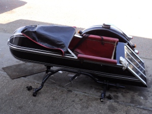
This is a copy of an S350 Steib on an LS200 chassis

Sidecar 2

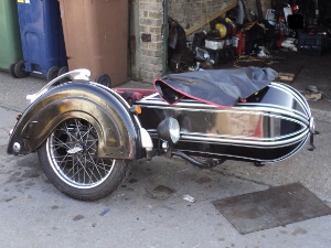
It’s in quite nice condition but is a right-hooker.

As you can see it’s not in bad condition but a new seat is required. There is one with it but while it is usable it is too bulky and is a poor copy of the original.

A problem is going to come up with fitting it because as you can see it is meant for fitting on the right side of the bike while in UK a sidecar is normally fitted on the left.

The sidecar is mounted on a Steib LS200 chassis which uses the German DIN standard sidecar fittings and it will mean sourcing a set of bike-side fittings to suit and will probably need a sub-frame to pick-up to that front mounting-point on the chassis.

Besides that the DIN fittings have the beauty that using them means that you have a sidecar that is both quick and easy to remove from the bike, not only that but you do not lose the sidecar alignment settings when you remove it, so when refitting the sidecar you do not need to re-align it.

However, a disadvantage of the LS200 chassis is that it only has a three-point mounting.

While this is adequate for on the smaller bikes (sub-350ccs) that the LS200 was intended for, on a more powerful machine it is better to have the more rigid four-point mounting and it will be necessary to arrange for this.

So, – –   Why fit a sidecar?.

Well it means that I can take the bairns with me when I go on events, it gives me extra carrying capacity for luggage and so on, and quite simply, I like them.

Riding a sidecar is totally different to riding a solo, it means learning a new and totally different set of skills but once you can handle an outfit they are great fun to ride, not only that they are great attention getters.

On Tap

Another problem that arose was with the fuel tap.

Panther only provided mounting for a single tap in the tank, with a balance pipe between the two sides so that you did not wind up with the tap side of the tank dry and fuel trapped on the other.

This does mean however that, unless you have a fuel tap with a built in reserve function, when you run out of fuel you will wind up pushing the bike. A Panther is a heavy machine to push, not only that but the nearest fuel is always in the opposite direction to the one you are pushing!.

To further complicate things, rather than use the common tank outlet size of 1/4 inch BSP they opted to use the rarer 1/8 inch BSP size, (you should realise here that with the pipe thread sizes, (British Standard Pipe) the dimension refers to the bore of the pipe and not the OD of the thread) it so happens that with this design of tap there is no difference in the internal bore of the actual tap with either size.

The tap I had was the common ENOTS hexagonal body type and it did have a reserve, but this was seized so I went looking for a replacement.

Tap

The seized fuel tap

I found a number of sources which listed this tap in both 1/8 and 1/4 inch sizes but when I tried to order one I was informed by them all that the 1/8inch size was “out of stock” and they had no idea when they would get any in, but they could supply the 1/8 inch size tap without a reserve.

So, nothing ventured nothing gained, I decided to try to strip the seized tap and clear it.

Tap2

Dis-assembled fuel tap.
The cork sealing disks are below the main tap body

As you can see the tap splits into three major parts, the top section, which contains the reserve mechanism, the centre which has the “On – Off” slide and the lower section which connects to the fuel line. The taps seals are the two disks of cork, each with a central hole, which are compressed one against either side of the centre’s slide by the other two sections.

There was no immediately obvious way for the reserve to come apart but as there was obviously an inner sleeve and an outer I decided to try a little pressure against the projecting end of the inner.

A suitably sized socket was placed at the lower end and the tap and socket nipped together in a vice.

Tap3

Tap being pressed apart

Given steady pressure the inner sleeve began to slip down into the outer, so it was pressed down until it was flush and then removed from the vice.

For all it had come most of the way through, the inner section still would not simply pull out using my fingers and since I did not want to damage the sleeve surface with grips I used a pin punch to knock it the rest of the way through.

Once it was apart the reason why it would not move was obvious in that the brass insert was blackened with corrosion but at least it was not pitted.

I polished it clean with a fine grade of wet and dry paper and then re-assembled the two sleeves and found that the reserve function was now working without problem so they were again disassembled.

Tap4

Tap with reserve stripped

As I had a pair of new corks for the tap, before fitting them they were soaked in  boiling water for a half hour to soften them.

The reserve sleeve was then wiped with silicone grease and whole tap then re-assembled with the new corks in the main body and I had a functional reserve tap for use on the old lady.

Sod’s Law Strikes

While the gearbox was out of the frame for new bearings I fitted the battery platform to the bike.

As I did not have one originally, this is a scratch built thing based on photographs.

It sits between the seat tubes, above the gearbox and is held in place by the four bolts securing the seat tubes to the engine plates so while the gearbox was out was the ideal opportunity to fit it due to easy access to these bolts.

Once the gearbox was finished it was refitted in the frame, as was the rear mudguard and everything was looking good.

Next step was to fit the primary drive chaincase. The rear half of this is held in place by one of the nearside seat tube bolts and by a second set screw going into a boss on the crankcase.

So the rear half of the case was offered up and went into place nicely, both mounting bolts lining up as they should so I started to tighten them down – – –  and immediately ran into trouble!.

The problem was that the new battery platform was fouling the back of the chaincase!

It wasn’t by much and I could have pulled the case home into place BUT I would not have been able to mount the battery securing post on that side.

After a few comments along the lines of “Oh dear!” and “What a thing to happen!” I settled down and took a careful look at things.

Whereas at first sight I had thought I would have to remove the rear mudguard and the gearbox again just to gain access I realised that by taking the magneto off the motor and working through the slot left for the clutch cable to go through I probably could get the battery platform off, but to do this I had to remove the primary chaincase again.

The effort proved successful and I modified the carrier to give the necessary clearance, not even a 10-minute job.

Now came refitting it, using tweezers to fit the washers onto the bolts through the cable slot and wangling the nut on using a screwdriver in one hand holding the nut against a finger of the other to get it in place, holding it there with the finger tip and turning the bolt head with the other hand until the thread caught.

Finally, aided by a little creative use of language, I had the platform back in place and when the chaincase was put in place there was clearance as required, all it means is that the battery will not now be sitting central over the engine plates.

As I had the back of the primary case in place now I took the chance and fitted the clutch assembly in place before calling it a day.

Bearing Up

Now that the new bearings have arrived it’s time to fit them.

Steel bearings into an alloy casing- -that means heat the casing to expand it.

The alloy expands more than the steel so by heating the case the old bearings will drop out and the new ones can be dropped in.

So it’s into the kitchen with a piece of plywood to protect the work top, some shop-rags, the new bearings and the inner and main casings.

I’ve already extracted the studs from the casings so they will sit square on their faces on the plywood  and the new bearings are unwrapped and put ready to hand.

The first casing is put into the oven, 10 minutes at Gas Mark 7 gets it hot enough that when a moistened rag is rubbed across it it sizzles so it’s taken out of the oven(GLOVES!) and rapped square and flat, open end of the bearing cup down, onto the plywood and the old bearing just drops out.

Smartly turn the casing over so it’s sitting open end up on the plywood, wipe the bearing mount clean with the shop-rag, drop the new bearing into place and then weight the bearing down to make sure it stays hard home in the casing as it cools and that’s the job done.

The second casing is now put in the oven. By the time that it has heated up the other casing has cooled enough to grip its bearing firmly and so it can now be put to one side and the whole process repeated with the second casing and bearing.

While the second case is cooling you have time to remove any evidence of your use of the oven from the eyes of S.W.M.B.O. and then get the casings etc. back into the workshop.

G/box Contents

Set out for re-assembly

Each of the bearings is held in place by a circlip and these pop easily back into place so the bearings are fully home in their housings.

Next thing is to install the output gear into the output bearing. This is a tight fit so it needs to be pressed home, easy answer is to pop over to Bob’s and use his press rather than codge up something, so with that gear now in place it’s time to rebuild the ‘box.

The gear cluster is assembled with the selector assembly meshed in on it and the whole lot offered up to the main casing, a little wangling and the layshaft end slips into its bushing, the end of the camshaft does likewise and the whole assembly slides into place.

The mainshaft is quickly slid into place through the output gear to lock things in place, the first gear pinion slid onto its end and that’s it.

main case

Gear cluster in place

All that’s left to do is fit the indexing pawl in place, put the bearing rollers in place on the cam-shaft and the inner casing can be put on and bolted up.

inner case

Inner casing bolted on

Once the inner case is in place then all that’s left to do is to fit the kickstart ratchet, match up the timing marks on the cam-shaft and the gear-change mechanism, wind up the return spring on the kickstart shaft and then fit the outer case with the foot levers and the rebuild is finished.