CRUNCH TIME ON THE COMBO

I’ve had a problem with the gears on the BMW combo for a while now, what’s happening is that it keeps jumping out of second gear under load and then dropping back in with a crunch.

I’ve been working round it by doing a double change up into third from first and not using second but that’s not fixing it and it’s a wide gap between first and third.

I recently had the chance to get another gearbox and jumped at it so now it’s time to change the gearboxes over.

As the sidecar limits access on one side, what is an easy job on a solo becomes a bit of a fiddle and the fact that it’s a /7 power train in a /2 frame does not help since it’s a tight fit!.

First thing is to run the rule over the replacement gearbox, all seems ok, changes gear without problems but the neutral switch is damaged, one of the electrical connections has been broken off, well I’ll just swap over the one from the current gearbox while I’m doing the swap.

So it’s out to the bike and get started, I need to clear the decks round the gearbox so we start by removing fuel tank and then the silencers.

Then it’s a case of take off both carburettors and their associated plumbing, I’ve left them attached to their cables and tucked them away at the front of the engine unit.

Now I need to remove both halves of the air-box. Left side comes away without problem, well it needs to, to be able to allow for the filter being changed but the right side hangs up, it’s not till I’ve removed the securing nut completely that I find a washer jammed in the slot that’s meant to allow the cover to slide off to the right side of the bike by just slackening the securing nut.

As the engine breather hoses go into the side castings of the airbox the easy way to get these covers off is to remove the top cover over the starter motor, because the ignition coils are positioned on the frame just above this cover it’s “a bit of a fiddle” to get it off and then we have the decks around the gearbox cleared for action.

But we’re not ready to remove the gearbox yet!, it’s still connected to the bike itself.

A BMW has a shaft drive and the shaft itself has a universal joint that bolts onto the output flange of the gearbox. This joint is under a rubber bellows and runs in oil so that needs draining and the bellows pushed back to allow access to the four 12-point head bolts securing it. Space is limited by the bellows so this is another right fiddle, and replacing them can be worse!.

As clearance with the rear sub-frame is tight it makes sense to remove the clutch operating arm, remembering to catch the return spring as it drops clear.

Now we can go round and slack off the four mounting bolts for the gearbox proper, as I have the combo’s battery mounted on the sidecar I have the main ground return from the battery secured to the lower right of these (remember this combo is a right-hooker!).

While it should now possible to remove the gearbox, clearances are VERY tight and to give more space the trick is to remove the rear swing fork pivot pins and move the complete rear wheel assembly back, it only needs to come back about an inch to make all the difference but of course up till now the bike has been standing on its wheels.

This means getting the jack out and lifting the rear end of the bike enough to drop the centre stand, because the bike has a 15inch rear wheel rather than the original 18inch, as well as a 16inch front wheel, to just try to simply lift her onto the centre stand as normal risks a rupture! But once you have her lifted up, dropping the stand becomes a safety measure, think of axle stands on a car.

Now to loose off the rear swing arm! First thing is to undo the rear brake linkage as this will prevent the wheel from being pulled back, undo the bottom ends of the rear suspension units, take out the bearing support pins and pull the wheel back.

Now comes the gear-change parts, this bike has the Kinematic assembly and the simple wire link has been updated with a rose-joint assembly.

There’s a lock-pin you need to remove from the front rose-joint that then allows the joint to split, once that’s done simplest way is to just drop off the entire left side footrest assembly.

Now the gearbox can have the mounting bolts removed, the top right one is a nut onto a stud into the main engine block and it is easiest to remove this completely, the gearbox can then be lifted clear, remembering to disconnect the neutral switch as you bring it away.

As mentioned before, I need to swap the neutral switches between the two gearboxes. I also need to fit the clutch pushrod into the replacement gearbox as this cannot be done with the gearbox in situ.

Next thing is to simply have a cuppa have a good think round and make sure nothing has been forgotten about before fitting the new gearbox in place.

While things are opened up it’s a good idea to clean and re-grease the spline drive on the clutch. This needs a black moly HP grease, but don’t overdo it! You don’t want any of that on your clutch friction plates!!

Now you offer up the box onto the bike, remember to fit the wires onto the neutral switch, it’s a real bitch of a job fitting them when the box has been installed, with the clutch push-rod pressed back into the gearbox align the input shaft with the centre bore of the clutch and slide the gearbox into place.

Once you have it home on the engine casing you can refit the mounting bolts and the stud. When you have that done it’s just a case of refit the rear swing fork into the frame and you can have the bike back on its wheels. Remember that you disconnected the rear brake!!

Then it’s just a case of reversing the disassembly work, fill the gearbox with oil, put about half of the spare gearbox oil into the swing arm and the jobs done.

Quick trial and find the neutral light not working, as this inhibits the starter it means the engine won’t start so it’s down and check the switch connections, I’d had a meter on the switch to ensure it worked before we started.

One of the switch terminals should go to a ground at one of the gearbox mounting bolts and this wire had broken at the tag of the terminal held under that bolt.

Sounds an easy fix, BUT, – the wire is now the exact length to reach the mount bolt tag, there is no extra length to allow it to have the end stripped back and fitted into a new tag and then to fit this under the bolt head!

Only access to this wire now is from underneath the bike so its a case of preparing an extender piece of wire and then to grovel alongside the bike, reaching under it, preparing the wire from the switch and then crimping on the extender, sounds easy but you try doing it!. Anyway, I managed it and made off the new connection under the bolt head.

Key back in, ignition ON and I’ve a working neutral light, try the starter and the engine turns over so next it’s a case of fuel on, hit the starter and she’s running again, time for a road test.
BLOODY TYPICAL!!

Well I’ve just been out in the garage to fit the new barrel onto the Panther only to find I’ve made a major cock up.

I had the barrel in place over the crankcases, slid the gudgeon pin into place, circlip fitted in place and slid the barrel down to seat on the cases and – – – IT DIDN’T BLOODY FIT!!.

The barrel spigot was too large for the cases!

So out with the circlip and gudgeon pin, barrel off the bike again and start the inquest.

Vernier out and check the spigot outer diameter against that of the other barrel and it was definitely larger, What’s going on?.

Sudden thought “It can’t be!” but measure barrel lengths. The old barrel is 3mm shorter than the new!.

Yes, the barrel I had had bored, the one that had a slipper piston in it and was tagged as being for an M100 is in fact for an M120! Just what I need!.

When I first built up the bike I’d got a job lot of spares as well, all said to be for the M100

There were 3 barrels, the one I’ve been running on, the one I now know to be from an M120 which has the new bore and piston and one other M100 barrel (Yes, I’ve measured it to be certain!). I know, I should have checked but the possibility never crossed my mind, especially as it had come with a slipper piston in it and the M120 did not use slipper pistons.

So a closer look at the two M100 barrels. There’s the one I’ve been running on and the “spare”. The spare turns out to have been bored out to plus 60thou while the other is on STD bore.

What is the wear like on them?. I used the old dodge of checking the ring gap in the unworn base of the bore and at half stroke and the “spare” comes out best with an increase of only 4thou.

The other barrel is about twice this, still plenty of life there but I decide I’ll put new rings in the “spare” and use that since I’m unwilling to bore either out for the Rover piston. Why had I not used this barrel originally? Quite simply because I had a set of new piston rings “in stock” to fit the barrel I did use.

So it’s now a case of clean up the outside of this barrel with the wire brushes and give it a coat of paint.

I got onto POC Spares for a set of new rings. I placed the order at about 10.00pm on the Wednesday night, parts arrived on Friday morning!! Well done to Old Foxy!!

Of course new rings meant that I had to set the ring gaps. I used the old advice of “4 thou for every inch of bore” and had to open up all three from a tight 10thou.

I cleaned out the ring grooves in the piston using the old rings to scrape out the crud, the middle ring had been a bit tight in its groove but all 3 are now an easy fit in their groove.

Because it was an old piston and I was not happy with the condition of one of the gudgeon circlip grooves I decided to fall back onto older technology and use gudgeon buttons rather than circlips, there’s a choice of materials here. My old Triumph uses these as standard and they’re phosphor-bronze, I know some of the racing boys are using Teflon or there’s also the option of aluminium.

If I choose phossy-bronze, well it’s not an easy material to work with since it work hardens on sight, I’ve looked into Teflon but this means buying an industrial length bar of the stuff and it’s not a cheap material so it looks like I’m going for the aluminium option, I’ve a foot length “off cut” of inch bar in stock so it’ll give me an excuse to play on the lathe.

So first thing is to work out just what’s needed, sit down with the piston, the gudgeon pin, a vernier, a sheet of paper and a pen to work out dimensions and sketch out what’s needed, then it’s out to the lathe.

First was measure the length of the gudgeon pin, subtract that from the bore dimension and half the result. This gave me the length I needed for the gudgeon buttons, next was the diameter of the pin and then its bore, what was needed was a “top hat” to match these dimensions.

Pop the ally bar in the lathe and skim about an inch and a half length of the bar down to 7/8 inch diameter and check against the piston, I used the old piston from the M120 barrel as a gauge for this.

The bar was a tight fit in the piston so I skimmed another couple of thou off it and tried again, an easy slip fit!.

Next step was to skim the last 10mm of the bar down to be a snug fit in the bore of the gudgeon pin itself, as the pin is taper bored this proved a bit fiddly but it was managed.

Next was bore a 3mm hole down the middle of the bar, part off the first button to length and then repeat the whole process.

Snag here is that these buttons are flat faced, but they have to go against a round bore. A look on Google gave me the required clearance to skim a shallow taper onto the face so that only the central few mm of the button was able to touch the bore and as they have to run with a slight clearance to the bore, same as the piston skirt, it was a simple job to skim that in.

Now the acid test, put the buttons into the pin and try it in the bore, an easy fit with a nice clearance to each side, jobs a good ‘un!, now to build things up again.

A not uncommon trick with a rebuild is to put the piston into the bore first and then lower it onto the head studs, sliding the gudgeon pin into place and fitting the circlips before sliding the barrel into place.

What isn’t said is that it can be a right fiddle getting the small end eye to line up with the gudgeon pin bores at all as the con-rod keeps trying to fall forward, and then you have to get the match exact enough that the pin will slide home through both the piston and the small end, remember that there is no clearance between these, it needs an exact match. At least there was no trouble with fitting the pin circlips since I was using the buttons.

After that it was just put everything back in place, believe it or not the biggest fiddle was replacing the exhausts!.

What is needed here is for the flange on the pipe to fit flush against the stub on the head. If you try to put the complete pipe and silencer in place as a unit, the flange will be on a tilt against the stub and you will not be able to pull them flush to using the retaining nut to get a seal, you need to have just the pipe in place and pull up the nut while wangling the pipe around to make sure everything mates up square before rotating it into place and fitting the silencer last, – – – and then you have to repeat on the other side!.

All that’s left to do is fit the carb, then the tank, add some fuel and give her a kick.

Story book ending is to fire up first kick and settle to a steady tick over.

Well second kick the old bitch kicked back and it took another couple of kicks before she was running and the carb needed setting up.

On initial kick over compression was down but after taking a couple of miles run it came up to reasonable and it’ll take a couple of hundred miles to bed the new ring in so all in all I’m happy with the result, just have to see how much oil she’ll be using.

What to do with the rebored M120 barrel? Well I’m considering skimming the spigot down to suit and shortening the barrel, this would have to be done on a mandrel but it is possible, or I could always source another M100 barrel and bore that to suit the Rover piston, it’ll depend on oil consumption once the rings have bedded in.

Getting Bored

The old Panther has been getting a bit greedy lately, in fact it’s been getting so that I needed to top up her oil just about every time I filled her petrol tank.

Now Panthers are known for their thirst for oil but this is a bit extreme, even for one of them and so it was obvious “something needed to be done!”.

One reason given for their thirst is their old fashioned oil ring technology, straight out of the early 1930’s!. Bearing this in mind, as well as the fact that the old girl had been rebuilt onto a worn bore and that I’d put another 4kmiles at least onto that, I decided to try a new bore.

There is a conversion available through the Panther club where you replace the piston with one from a Rover 3.8 car engine, This involves some modification work to be done on the piston but an already modified piston is available through the club, as are all the required gaskets for the job.

It means over-boring the barrel to plus 75thou but there is sufficient “meat” in the barrel to accept this and still be able to take the next oversize! These old girls were well built though, and to last!!.

When I originally rebuilt the old lady there was a choice of barrels to use. The one I selected had the better bore but a broken fin and I used this in preference to the cosmetically better but worse worn barrel so this is the one that has been bored out to suit a club piston.

I had asked for the barrel to be bead blasted before being bored but this was not done so I had to set to with wire brushes on the barrel once I got it back to clean it up for painting.

It was then given 3 coats of black “Smoothrite” from a rattle-can and put out in the glazed porch to harden off in the sun for a week.

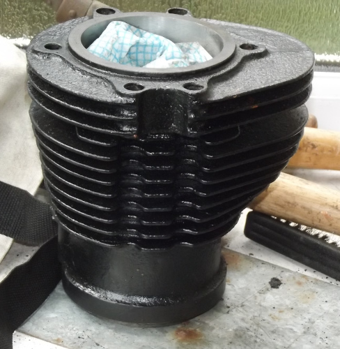
Barrel

The barrel resplendent in its new paint

All this could be done before a spanner needed to be set on the old lady herself and that moment had now almost come!.

A decision had to be made as to the cylinder head. This would need to be repainted to match the barrel. It’s a cast iron head so the obvious seemed to be to just black it the same as the barrel. BUT! An option appeared.

Back at the time she was originally built the “go to” option for the more sporting bikes was to have a bronze cylinder head, aluminium alloy technology not yet being up to that job and, knowing that there had been a number of bronze heads cast for Panthers, I could paint the head in bronze!. Decisions! — Decisions!!.

Anyway before I could do the head I had to remove it from the bike so it was out into the garage and start the dismantling work.

As always stripping off the ancillaries takes longer than the actual dismantling but the old lady soon stood with her head stripped off.

Looking into the barrel I could see the piston crown was oily so that explained the high oil usage!.

I tapped the head through-bolts down to level with the top of the barrel and then left her there while I got to work on the cylinder head itself.

A session in the wash tank got the head cleaned of oil and then it was a case of out with the wire brushes to get it down to as near bare metal as I could before painting began.

Also required before paint was applied was to mask off the exhaust stub threads and the joint faces, it’s surprising just how fiddly a job this is!

I went onto ebay and got a tin of a high temperature bronze paint, paint intended for brake callipers and I’ve given the head a couple of coats so now we’ll just have to see how well this paint stands up to the temperatures round the exhaust stubs!, if it come to the worst I’ll just give the head a coat of cylinder black and go back to standard.

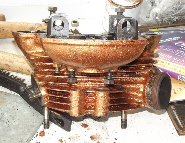
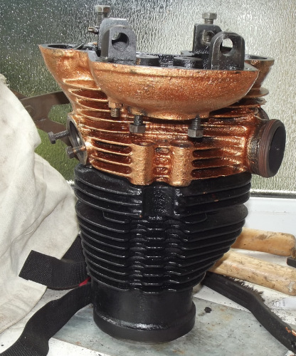
Bronze Head Head & Barrel

The cylinder head in bronze and it fitted in place

It looks a bit bright here but it should dull down with a bit of use, otherwise I can add a spot of black to the paint left in the tin to mute it down a bit and give the head a coat of that.

A snag when re-building a Panther engine is that the standard cylinder bore is 87mm. The biggest of the easily available “Terry’s” piston ring clamps however only goes up to 85mm. It can be stretched to cope with 87mm but it won’t cope with the 89mm Rover piston so the usual assembly trick of sliding the barrel onto the piston with the rings in a clamp won’t work, especially since the overboring takes out most of the usual taper lead-in from the barrel base.

This means I’m going to have to assemble the piston into the barrel and then offer the barrel and piston together up to the crankcases, slide the gudgeon pin into place and fit the circlip, what could easily be done on my own has just become a two person job, one to handle the barrel and the other to fit the gudgeon pin!

Anyway the original barrel is now off and I’ve got the crankcase face all cleaned down, I’ll use some Hylomar as a sealant here on re-assembly to try to keep the joint oil-tight.

A Bit of a Wobbler

When out on the BMW sidecar outfit at the weekend I noticed a trace of steering wobble that was not there before.

Once back home I checked things over.

First check was tyre pressures, especially the front wheel. These checked out in spec.

Next was steering head bearings, and the front wheel bearings while at it, these were all free and had no play so that was something else crossed off the list.

Next in line came the rear swing fork and wheel bearings. Some play was found in here in both horizontal and vertical planes.

This cleared the swing fork bearings, if these had been at fault the play would have only been found in the horizontal plane, so new rear wheel bearings were indicated.

Thing is that the rear wheel in my combo is an EML unit and NOT a BMW one so the bearings in it are different to those shown in the spares book, and, as I wanted to have the new bearings “in hand” before I started work, I needed to know what they were.

An email to EML themselves failed to receive an answer so I tried the BMW lists on the internet. I received an answer from a member in the States who has an EML outfit with the bearing numbers and I soon managed to get a set from a local bearing specialist.

So, to work!. First thing is to get the bike up onto it’s centre stand. Not as easy as it sounds because the reduced tyre sizes I run have lowered the bike. It’s only by about an inch but the roll-on action of the centre stand no longer works, you need to do a dead weight lift of the bike to get it high enough to lower the stand and it’s b—-y heavy, in fact it needs the use of a jack to remove the risk of a rupture!

Next is that as I am running a non-standard tyre, a wider section car tyre, on my rear wheel the normal BMW quick removal system does not work, the tyre will not clear the brake shoes and drive hub, I have to remove the wheel complete with the rear bevel box and this is not as simple a job as it seems.

First is to disconnect the rear brake rod, next drain the oil from the drive shaft housing, undo the 4 nuts securing the bevel box to the swing arm, remove the lower mounting bolt from the right hand suspension unit. (Oh and it gives more clearance to work if you remove the offside silencer to start with)

Now you can remove the rear wheel spindle and pull the entire assembly back out of the frame, and it’s heavy!!.

Once I had the assembly clear I could lift the wheel away and have a look at the bearings. Sure enough they had been fitted with the bearing numbers facing inwards so I could not read them! Typical!!.

As my rear wheel is literally a car wheel bolted onto the bike hub the next step was to remove the wheel from the hub, just a case of undo the three lug nuts. (The wheel I’m using is from a Citroen car, typical French skimping on an engineering job! Just use 3 lug nuts when everyone else is using either 4 or 5!!).

With the hub clear it was now just a case of using a long drift to punch out the old bearings, heart in mouth moment as I checked the bearing numbers then the relief of finding I had the correct bearings in hand!.

Replacement was simple just thoroughly clean the hubs bearing seats and bore, grease up the new bearings and the spacer and hub bore and fit the new bearings in place, the old bearings make a good pressure bush for this and all that’s left to do is re-assemble everything and find that the wheel is locked solid when I nip up the spindle nut but will turn when I ease the spindle nut!

Guess who forgot the spacer between the hub bearings and the drive?.

On the original BMW hub this is captive, held in place by a separate grease seal between the (open) bearing and the drive. EML widened the gap between the bearings by substituting sealed bearings for the bearing/grease seal pair and using a loose spacer on the spindle instead. An improvement giving a stronger hub for sidecar use BUT!.

This resulted in blue air and a frantic search for the missing spacer!.

Once it had been found and installed, the wheel was now turning easily and I could look to refitting the assembly onto the bike.

Simple way was to put a 4 inch piece of timber down and stand the wheel assembly on that. Doing this brought the bevel box up into near its correct alignment with the rear fork and made it a simple matter to bolt it in place and refit the suspension unit and the rear wheel spindle, not forgetting the rear brake actuator rod.

An AHA! moment

Well I’ve been busy on the LE again and think I may have found the ignition problem.

I needed to know what depth I had between the top of the ignition unit’s top plate and the bore in the end of the crankshaft, this meant taking out the fixing bolt and when doing this I steadied the shaft from turning by holding the unit, as soon as I had eased the centre bolt a little I felt the bob-weights move under my fingers when they had been solid before.

On trying the unit I found the bob-weights would now open out readily. I re-tightened the centre bolt and found they were locked up so that while the engine had been running it had been locked on full retard, no wonder performance had seemed lacking!. It looks like the last person working on the engine electrics had over-tightened the retaining bolt and jammed the unit.

Hopefully the unit has not been damaged by this but we’ll have to see.

I’ve since tried her up the back lane and she seems a bit livelier, but I’ve found that I omitted the seal between the carburetter and the inlet manifold when I put things back together last time. On having a look at the seal it appears to have been cut from a piece of old inner tube, it’s certainly been either knife or scissor cut so I’ll need to get a new one up.

I’ve just totted up what bits I now need, it may be small stuff but it totals out at about 21 quid so It’s worth sending down for them.

It’s amazing how it’s a number of small things are giving the problems now! I had thought that all that was wrong with her was the corroded water pipes! But I suppose that’s what happens when you take on a rebuild.

A New Addition

I decided to go the drill blank route to make the ATD extractor so ordered up a 3.5mm drill blank and a 1 inch long 5/16 BSF bolt along with a couple of nuts.

I now needed to determine the requisite lengths for the extractor parts, I did have suggested dimensions from an internet posting but I’ve learned to always check these before use.

To get the dimensions I need to remove the front cover from the engine. Under this cover is an inner cover carrying the two ignition coils and the points. Behind this cover is the generator and flywheel, the ATD mounting onto the nose of the flywheel with a bolt going through the ATD plate into the hollow nose of the flywheel.

I immediately ran into a problem!. The LE is a small machine and is built low to the ground, to access the front end of the motor you need to not only get down on your knees but have to grovel and I am no longer as young as I used to be.

This pushed me into deciding to do something I have thought about for a few years now, but with the other bikes I had managed by getting a wheeled stool, I decided it was time to get bike lift!.

A problem I have with this is space, a lift will have to be kept between two bikes with another on it, I’ll need to wheel it out to work on a bike but then put it away when finished for the day as I have to get the combo in as well, (insurance demands that it is garaged any time it is left unattended!).

So it was a case of get a notebook and pen ready and fire up Google!.

I’d already decided to go the whole hog and get a table type lift rather than a simple frame jack, (these are not really suitable for use on a BMW anyway) so it was a case of see what was available.

Having recovered from the shock of seeing the prices being asked for the powered types (and realising that my little compressor was not man enough to power them!) I decided it would need to be one with a hydraulic jack.

This brought the prices down to the “reasonable to pricey” range.

Next was size, turns out that some are shorter than a bike so it has to sit on the front wheel and a jack under the frame or a centre stand, an under frame jack is not suitable for a BMW so one of these would mean putting the bike on its centre stand then dragging forward to the front of the table again before lashing it down to keep the rear wheel aloft. The idea is to make it easier so beggar that type.

Anyway I settled on one from CJ Autos that would fit into the available space, was a reasonable price and available; It’s in the garage now, fits nicely into the space available, the LE is up on it now and I’ll be able to make a start on producing the extractor tool tomorrow.

========================

It’s now tomorrow and I’ve been out in the garage most of the afternoon, the morning was largely spent walking the dogs.

First thing was to get the combo out and get some space to work in. I moved the table out into the space to find it has the “shopping trolley” problem in not wanting to roll straight, a nuisance when it weighs over 100kg but liveable with when you know about it.

Next thing was to run the LE up onto it and secure it, the front wheel clamp works but is awkward to wind in when one hand is supporting the bike, I’ll have to look into this when putting one of the bigger bikes up on it!, a bike support mount might be a better idea

Anyway I added a couple of the trailer straps to steady the bike before I tried to lift it, then it was fit the pump pedal and try it out.

Nae bother! Up she went and I popped the locking bar into place.

I had to remove the front cover from the LE engine unit next and straightaway I found a snag.

Clearance between the front mudguard and the front of the engine is limited and I found that while I could remove the bolts securing the cover there was not enough clearance to remove the cover. Normally you’d put the front wheel over to one side and then there’s plenty room but the wheel clamp prevents the wheel twisting.

Fortunately the stand on an LE does not lift the bike off its wheels so I could safely roll her back far enough to get the wheel to turn far enough for clearance but could not have done it with a BMW, one lesson learned!.

With the cover off and the table raised there was no need to grovel to see what I was doing. The first thing was to have a look at the ATD and I found it locked in the full retard position, no wonder the old lady would not run properly!

As soon as I eased the pressure on the centre bolt the bobweights came free, all that seems to have been wrong is that the ATD had been overtightened on the taper so we’ll give it a try now before trying to disassemble any further.

While I had her up on the table I found that one of the rubber coolant pipes was leaking. The extra height let me see that the hose-clip on it was not on square and so the pipe was not snug onto the stub on the water jacket. Due to tight clearances it was a right flaff to get the clip on square, but that’s why it was on squint in the first place.

Fortunately it was the return pipe so I’ve only lost the header volume of the coolant, but I’ll have to top up the radiator before I can run her. Snag of a watercooled machine in winter, I’ll need to get some more anti-freeze and de-i water to top up with.

Then it was just drop the table and offload the bike. The table then pushed back to where it is stowed easily enough but I don’t fancy trying to move it with a bike on it, too bl–dy heavy.

As it is it sits between two bikes and the LE is run up onto it, the extra height means the LE’s handlebars and controls clear those of the other two and the combo fits in nicely behind it.

The snag I found with clearance at the front will only affect a bike where you need access to the front of the motor but it brought home the advantage of having a full length table rather than the cheaper option where the rear wheel is left over open air once you remove the ramp and of having sufficient width, I had seen one lift that was basicly a length of 6inch channel!. The one I’ve gone for has a 550mm wide table and would fit between two bikes in my shed but most I saw were in fact wider (and pricier!).

Timing Snags

Following a good firkle round on the LE Velo Clubs website and mining the data on their Forum I’ve come up with the information needed for checking the ignition timing.

Apparently on an LE it fires 29º BTDC. Considering that I have another side-valve boxer motored bike and it fires at 42º BTDC this seems a bit retarded but that’s what it says, both motors are just about square so it’s not that one is a longer stroke than the other.

There is also the fact that this equates to 0.26 inches of the piston down the bore as well as dimensions for the flywheel tool so this will help making up the special tools the book requires.

Only other thing needed is the extractor bolt for the ATD unit.

This is supposed to be available through the club spares scheme but is currently listed as “Not Available”, Typical!!.

From the picture it’s similar to the BMW tool for this job but the BMW one is metric threaded and will not fit, again Typical! as I have two of these!

Daft thing is that when I made the BMW ones the difficulty was in getting the correct grade an metric thread, now it’s the other way round as I’ll need a long high tensile 5/16 inch BSF bolt to make the Velo one and no-one keeps BSF stuff on the shelf these days!.

A possible snag here is that the tool has a long, slender tip, it has to be just under the core size for 2BA to go into the end of the crankshaft and that’s about 1/8 inch, it’s probably more practical to insert a suitable drill blank into a 5/16 inch bolt to make it as skimming down a bolt to this size on a big lathe is not the easiest of jobs.

ADJUSTMENTS (2)

While I was looking through the box of odds and sods that came with the bike I had seen a chunk of metal I had not recognised the purpose of. It was not till I went to make a new handlebar end plug that light dawned and I realised that it was in fact the missing plug so that saved me a job.

Having the plug “in hand” I now needed to fit the new grips.

First was the clutch side so I warmed the grip to soften it a bit and swilled a drop of petrol inside it to act as a lubricant. The grip was a tight fit on the handlebar but eventually submitted and was slid into place and the end plug fitted so attention was turned to the twistgrip side. To fit this one it was so tight I wound up removing the twistgrip sleeve from the handlebar before it also gave up the fight and was wrestled into place.

It was now time for another road test and I could feel that the little lass was not happy, felt like the ignition was badly retarded so it was back home and read up in the books.

Turns out that there is no figure posted for the ignition timing, you set the engine in position with tool LET 953, you can then check the flywheel is in the correct position with tool LET 952 and if that’s right you can set the ignition. There is an index mark on the flywheel that shows TDC and you set the ignition timing to that on full retard

I can hire the tools from the LE Club, but neither will be difficult to make. Snag is if the flywheel is in the wrong position, to remove it means another two special tools and you also have to remove the oil sump to block the crankshaft from twisting as you slacken off and re-tighten the flywheel securing nut. Why could Velo not have done it by making provision to block the flywheel the same way BMW did in their boxer twins?, easier for service, works just as well and you don’t have to drain the sump to do it, come to that their trick of marking the TDC and ignition advance points on the flywheel would be an improvement as well . It’s much easier to work on the big Velo singles!.

Adjustments!

After a bit of thought I came to the conclusion that a probable cause of the problem could be that I was not getting full opening of the throttle, especially going by the excessive free play in the twistgrip.

So I popped the carburettor off and had a look. Sure enough I was getting, at most, half throttle! No wonder she felt a bit flat!.

I tried taking up the free play with the adjuster on the top of the carburetter but this did not have enough adjustment so it was up to the other end to see what I could do there.

My LE is a composite of a MkII chassis with a MkIII engine unite. Can’t speak for the later models but mine is fitted with a involute scroll twistgrip and these tend to have more free play than the more usual “drum” type grips.

Looking at the twistgtrip I couldn’t see how it came apart so I posted a query on their Facebook page.

From the replies I found that there was a bar end fitting securing it in place, originally these bikes were fitted with an open end grip on their bars exposing this but my bike has been fitted with aftermarket closed end grips which had hidden this.

A blast of the heat gun persuaded the plastic gip to soften a bit, enough that I was able to remove the grip and once that was off it became obvious how to take the twistgrip apart.

Having had a look I saw that the inner cable was too long. I could try to move the cable nipple back along the cable a bit but I’ve never had success in trying to re-solder onto a used (and oily) cable.

The other option is to make up a cable stop to effectively lengthen the outer cable, looking round I found a suitable bit of brass bar so its off to the lathe!.

I soon had the cable stop made so next thing is to try it on the bike.

Well, it fitted in place without any difficulty but I now had the opposite problem, not enough free play! I had now spaced the cable too far out from the original stop.

As the cable had seated very deeply into the original stop all I had to do was convert the shouldered stop I had made into a simple spacer bush so the cable no longer bottomed out in the original stop.

Problem seems to have arisen because there are 4 different throttle cables listed for use on an LE Velocette so it’s 3 to 1 that I have the wrong cable fitted, problem is that with a hybrid bike like I have which cable is correct? Still, my little bodge gets the little lady up and running and is easily undone, next time I’ll probably just make up my own cable for her.

Now the reason I could not see how to dismantle the twistgrip was that a closed end type grip had been fitted, one in an inappropriate colour for a staid old lady like the LE so I went and bought a pair of black rubber open ended grips for her.

Now looking at her, although it is as standard, the throttle side grip has a shiny metal end cap with an acorn nut on it to close off the bar end while the clutch side is bare, black, open handlebar end so I’ll have to do something about that, a bit more time on the lathe is in prospect!.

First Time Out

No excuse now, I’ve been out and taxed the LE! That means it’s now time for the acid test!.

So it’s on with the riding jacket and wheel the little lady out of the garage. Get my helmet and gloves out of the sidecar and we’re ready to go.

Fuel on, set the choke, turn her over a few times to prime the cylinders and then switch on and give her a kick.

On the LE, Velo described it as a “Footstarter” rather than a “kickstart” since it took so little effort to start the engine and it lived up to the name, a gentle prod and the engine is running.

Wait about half a minute to warm up and take off the choke and it’s into gear.

Bit of a crunch suggests the clutch needs adjusting but we’ll see to that later, ease the clutch in and we’re moving, easy pull away but feels a bit sluggish.

Into second gear and she pulls away nicely initially but soon runs out of puff.

I’m thinking “Last time I rode an LE it was smarter away than this, but hell, I’m used to the 800cc BMW.

Going up the hill out of the estate and it’s obvious something is not right so I turn right onto the main road, it’s down hill and I get into top gear, a quick check, ammeter showing a charge so the generator is working OK, oil-pressure up to 30psi so that’s OK bot there seems a lot of lost motion in the twistgrip.

Turn right back into the estate and back home.

First time out a run of less that a mile but a couple of problems have shown up.

Still she ran nicely, sounded sweet but badly down on expected performance.