Monthly Archives: February 2014

Breathing alterations

I’ve now got about 70 miles up on the old lady.

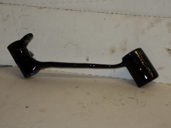
As said earlier she had a Amal Type 276 carburetter fitted rather than the correct Amal Type 89.

Major difference is that the 276 has a smaller bore so the old girl has been undercarburetted.

This model of the carburetter was fitted to the 500cc Panther of this period and I found it was set up as specified for that bike, not only that but it had the same type suffix on the carb body so I suspect that at some time the carb from the other model has been fitted in error.

Having a few miles up now, and on checking the plug finding her running rich even though there is a No.5 slide fitted and the carb set lean, I decided to bite the bullet and get the correct carburetter for her.

Options were to look for a used one or get a modern rebuild.

On checking with Amal themselves I found that the Type 89 was not available but the slightly later Type 289 was.

The difference between them is that the 289 takes its pilot air supply from the main air inlet while the 89 takes it from holes in the side of the body and I decided to opt for the 289.

After a bit of discussion with Amal I ordered a new body less the float chamber, I do after all have a NOS chamber on her now so don’t see the point of getting another one.

The new body cost just over £170 plus post and the inevitable 20% tax .

Two days later a package arrived in the morning post.

In it was a box full of paper shred packing and an “AMAL” box.

Box

Amal Box

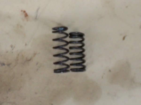
Inside that, wrapped in more packing, was a split new Type 289, already jetted and set up for a 1937 Panther M100 with a full “set up and tuning” leaflet plus an envelope containing the throttle slide spring and a new gasket for between the carburetter and its manifold.
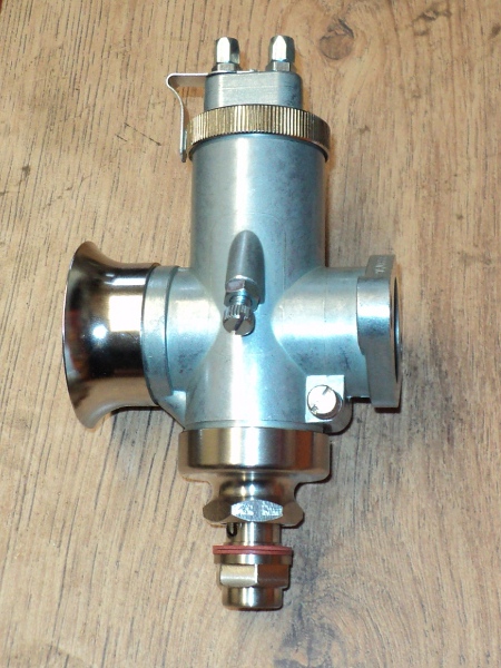
Amal 289

The New Carb

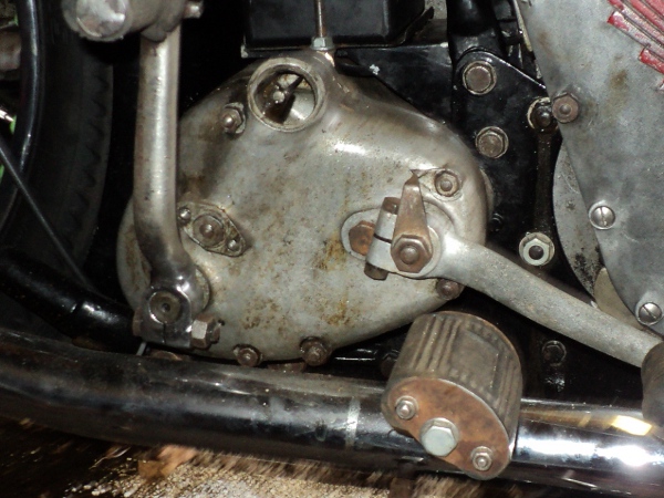
So, out to the garage and fit the new carb.

I had two worries here, the free length available on the throttle and choke inner cables.

First tried was the throttle, and it turned out that there was sufficient free length for the slide to “bottom out”, even when turning the handlebar from lock to lock so no problem there.

But when the choke cable was checked the slide was not bottoming, there was insufficient free length so the cable needed to be altered to suit.

The simple way round this is to shorten the casing of the cable, this has the effect of increasing the free length of the inner cable which is what we want and all that’s needed is an extra 1/4 inch of that free length.

This is one of those fiddly jobs that isn’t often done but if you do know how to do it, it can save you a lot of trouble.

The obvious way is to unsolder one nipple, cut the casing back and then resolder the nipple but this is easier said than done because often solder will not “bite” onto a used cable.

It is however possible to just trim back the outer casing itself without removing the nipple.

To do this you first slide the ferrule back of the end off the casing, up to the nipple and out of the way, this is probably the most difficult part of the process depending on how the ferrule is fixed in place, but using a sharp knife to knick round the casing at the ferrule’s base will normally do the trick.

You can then “winkle” the bit of loose casing cover out of the ferrule and the outer cover needs to be cut back to expose the metal coils anyway.

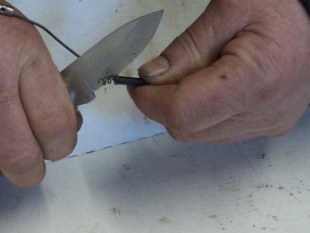
Then, using your knife press the edge of the blade between the end coils of the casing and then twist the blade to lever them a little way apart.

Step1

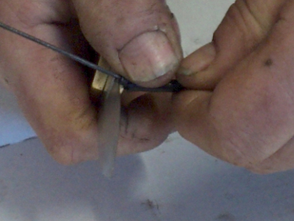
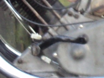
Opening End Coil of Casing

You can then turn the blade so as to take the free end of the coil over the inner wire and the casing can then be unwound away from the inner wire for a few turns.
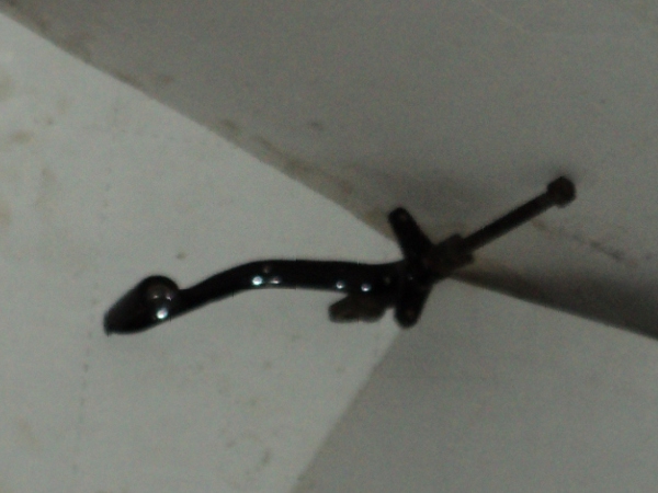
Step 2

Unwinding Casing

Once you have sufficient unwound then just nip off the unwound coils with a pair of cutters.

Step 3

Nipping Off Excess Coils

There will be a sharp “rag end” of the casing left projecting, this can be dressed off with a file or careful use  of a “Dremel” tool and all that is left to do is slide the ferrule back into place and refit the cable.

I’ve found this trick can be useful at the roadside once when I altered a clutch cable from one make of bike to fit another when its cable broke, meant the bike could complete the event and did not need to be “trailered home”.

In Drag

When I first took the old lady out for a ride I found that her clutch was dragging badly.

When you are setting the clutch up, the individual clutch spring tensions are adjusted until you get an even “lift” when the handlebar lever is operated and when I initially set this one up I had problems getting the spring plate to lift evenly.

As the springs are all identical then the amount their adjuster are screwed in by should be fairly close to each other and these were not.

This indicates that the springs are “tired” and should be replaced so I got a set sent up from the Owners Club spares scheme.

To fit them requires a bit of dismantling, on late models there is a separate dome cover over the clutch and to work on the clutch you just need to remove that but life is not so easy on the pre-war machines.

With these you need to remove the complete outer primary chaincase, to remove that you need to remove the footrest and to remove that the exhaust syatem on that side has to come off!.

Primary Drive

Primary Drive

Once the primary case is removed you have access to the clutch and the springs.

There are five springs in the Panther clutch, each fitting into a spring cup in the clutch face-plate and secured in place by a sleeve nut with a screwdriver slot in it.

Clutch Exposed

Clutch Exposed

I unscrewed one of these sleeve nuts, removed the spring and compared it against one of the new springs and found the old spring was noticeably shorter, it must have “settled” a bit over the years.

Springs compared

New and Old Springs Compared

Then it was merely a case of putting the new spring in the spring cup and fitting the sleeve nut, sounds easy but it’s not due to the spring pressure.

Since the adjusters are a sleeve nut rather than a screw you need a special screwdriver with a gap in the blade to allow for the stud that the sleeve nut screws onto.

spring tool

Spring Adjuster Tool

This shows the tool I used, it’s made from a bit of 1/2inch hexagon bar with a 1/4inch hole drilled down the middle and the end ground into a screwdriver blade.

By fitting it into a socket on a “T”-bar I can put an even pressure on the springs and turn the sleeve nut to engage it with the threads on the stud.

The springs were replaced one at a time and then all were tightened down till they were solidly coil bound.

They were then each turned back by four complete turns to give the base setting.

The clutch was then operated several times to settle the springs in their positions and then operated while watching the face-plate lifting.

The springs were then individually adjusted until the plate was lifting straight and even.

As on this occasion there was no need to replace any of the clutch plates there was no need to reset the free play in the clutch cable but if I had renewed the friction plates this adjustment would have been needed.

The effect of new, thicker, plates is to increase the free play in the system and there are two ways to adjust this out.

The obvious way is using the cable adjuster where the cable enters the gearbox but this is limited and there is also another adjustment on the internal lever inside the gearbox.

This adjuster is to be found under the small cover seen here by the kick-start lever.

 Adjuster Cap

Fulcrum Adjuster Cap

This cover is held in place by two screws, once these are removed the cover can be lifted off revealing an adjuster nut which alters the fulcrum point of the internal lever.

Adjuster Nut

Fulcrum Adjuster Nut

Since the underside of the cover is recessed to fit the adjuster nut, the simplest way to adjust this nut is using the cover to turn it.

However the cover must be screwed firmly in place before you can operate the clutch as it is the anchor point for the fulcrum.

Pedalling about

The last of the foot controls needing “adjustment” was the brake pedal and this was also the most awkward one to do.

When I got the bike it was in this shape and not knowing any better, I assumed this to be correct:-

Brake pedal old

Brake pedal “As Was”

Bent Lever

Bent Lever


As you can see the way the cables attach to it means there is a lot of “lost” motion of the pedal before there is effective movement of the cables.

Yes “Cables”, this old lady came with her front and rear brakes coupled together as standard.

At the pedal the top cable works the front brake, the bottom one the rear, all this back in the 1930’s, about 50 years before the Japanese manufacturers “invented” the system :^).

On closer examination it was found that the pedal lever was twisted at the point where it curved down and the toe-piece was bent in towards the bike.

In order to bend a steel forging like this it is necessary to get it up to high temperature, when it can be bent like warm toffee, so a gas torch was brought to bear on the job.

First thing to do was take out the twist and removing this almost completely eliminated the bend.

This had two other, connected,  effects though, first was that it very effectively removed the paint from the lever and the other that once the paint was removed an earlier repair was revealed.

At some time before I  got her the old girl has been dropped and this must have been the cause of the bent lever, however when being dropped the toe-piece of the pedal had also been snapped off.

This had been repaired by simply butting the two broken ends together and then brazing the joint up, so effectively the leverage to trhe rear brake was being taken by some brass brazing rod, Not an Ideal Situation!!

If the joint had been splinted as well then it would have been an adequate repair but not as it was.

To make a better repair the break was cleaned up, dressed and grooved.

The whole pedal was then set up on blocks so the toe-piece was correctly aligned and the parts “TIG-welded” together, this way the repair will be as strong as the original pedal was.

Once the lever had cooled down it was then dressed back and then given a coat of etching primer before having the imperfections made good with filler.

A few coats of primer/filler were then sprayed on and allowed to dry overnight.

Once this had been rubbed down smooth and level the black topcoats were added, followed by a couple of coats of clear lacquer and this was the result:-

Repaired Pedal

Repaired Pedal

Repaired Pedal2

Repaired Pedal

Now the cable is making a 90 degree angle with the lever arm when at full stroke, which is what is required, not only that but the “lost motion” has been eliminated, giving a better “feel” to use of the rear brake.