Category Archives: Panther

Panther motorcycle restoration

BLOODY TYPICAL!!

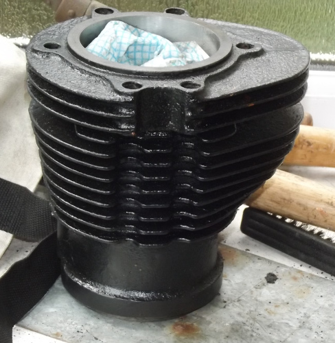
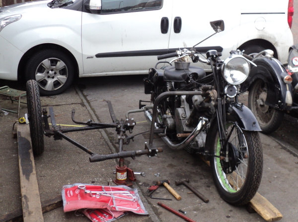
Well I’ve just been out in the garage to fit the new barrel onto the Panther only to find I’ve made a major cock up.

I had the barrel in place over the crankcases, slid the gudgeon pin into place, circlip fitted in place and slid the barrel down to seat on the cases and – – – IT DIDN’T BLOODY FIT!!.

The barrel spigot was too large for the cases!

So out with the circlip and gudgeon pin, barrel off the bike again and start the inquest.

Vernier out and check the spigot outer diameter against that of the other barrel and it was definitely larger, What’s going on?.

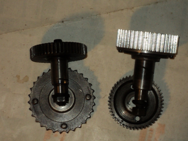
Sudden thought “It can’t be!” but measure barrel lengths. The old barrel is 3mm shorter than the new!.

Yes, the barrel I had had bored, the one that had a slipper piston in it and was tagged as being for an M100 is in fact for an M120! Just what I need!.

When I first built up the bike I’d got a job lot of spares as well, all said to be for the M100

There were 3 barrels, the one I’ve been running on, the one I now know to be from an M120 which has the new bore and piston and one other M100 barrel (Yes, I’ve measured it to be certain!). I know, I should have checked but the possibility never crossed my mind, especially as it had come with a slipper piston in it and the M120 did not use slipper pistons.

So a closer look at the two M100 barrels. There’s the one I’ve been running on and the “spare”. The spare turns out to have been bored out to plus 60thou while the other is on STD bore.

What is the wear like on them?. I used the old dodge of checking the ring gap in the unworn base of the bore and at half stroke and the “spare” comes out best with an increase of only 4thou.

The other barrel is about twice this, still plenty of life there but I decide I’ll put new rings in the “spare” and use that since I’m unwilling to bore either out for the Rover piston. Why had I not used this barrel originally? Quite simply because I had a set of new piston rings “in stock” to fit the barrel I did use.

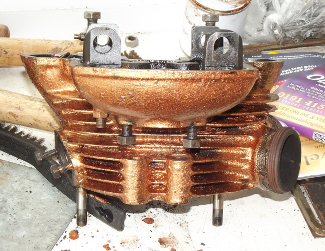
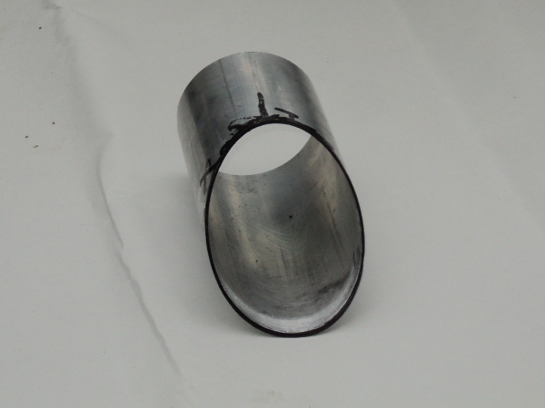
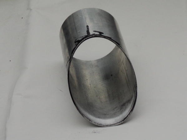
So it’s now a case of clean up the outside of this barrel with the wire brushes and give it a coat of paint.

I got onto POC Spares for a set of new rings. I placed the order at about 10.00pm on the Wednesday night, parts arrived on Friday morning!! Well done to Old Foxy!!

Of course new rings meant that I had to set the ring gaps. I used the old advice of “4 thou for every inch of bore” and had to open up all three from a tight 10thou.

I cleaned out the ring grooves in the piston using the old rings to scrape out the crud, the middle ring had been a bit tight in its groove but all 3 are now an easy fit in their groove.

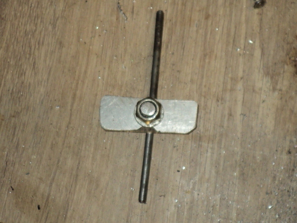
Because it was an old piston and I was not happy with the condition of one of the gudgeon circlip grooves I decided to fall back onto older technology and use gudgeon buttons rather than circlips, there’s a choice of materials here. My old Triumph uses these as standard and they’re phosphor-bronze, I know some of the racing boys are using Teflon or there’s also the option of aluminium.

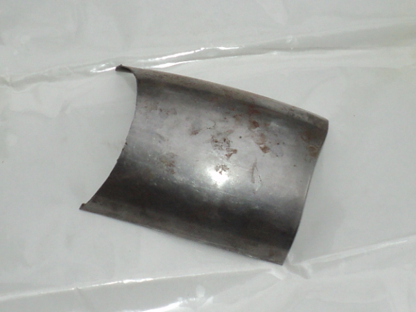
If I choose phossy-bronze, well it’s not an easy material to work with since it work hardens on sight, I’ve looked into Teflon but this means buying an industrial length bar of the stuff and it’s not a cheap material so it looks like I’m going for the aluminium option, I’ve a foot length “off cut” of inch bar in stock so it’ll give me an excuse to play on the lathe.

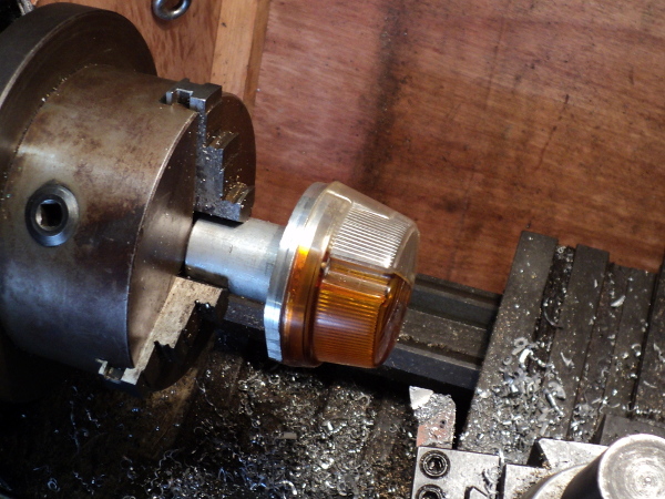
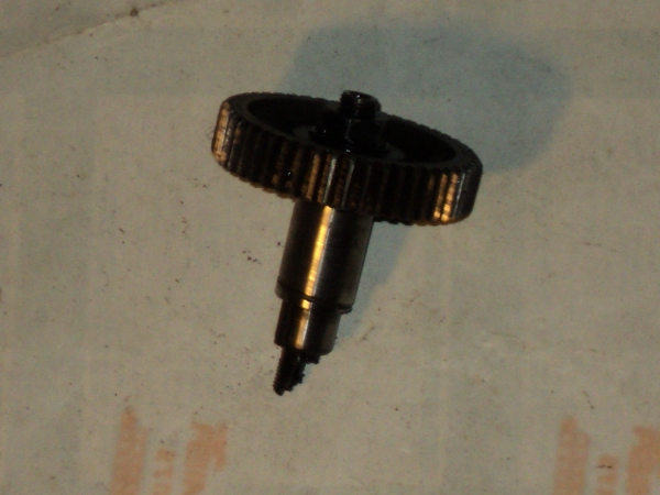
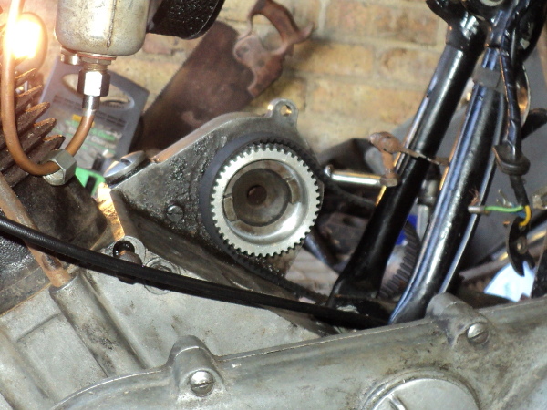
So first thing is to work out just what’s needed, sit down with the piston, the gudgeon pin, a vernier, a sheet of paper and a pen to work out dimensions and sketch out what’s needed, then it’s out to the lathe.

First was measure the length of the gudgeon pin, subtract that from the bore dimension and half the result. This gave me the length I needed for the gudgeon buttons, next was the diameter of the pin and then its bore, what was needed was a “top hat” to match these dimensions.

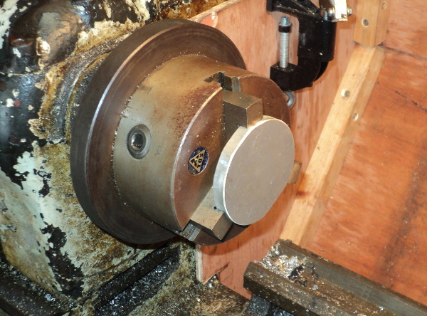
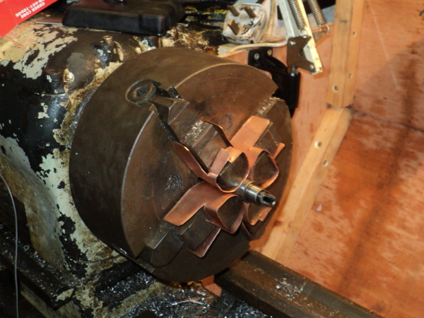
Pop the ally bar in the lathe and skim about an inch and a half length of the bar down to 7/8 inch diameter and check against the piston, I used the old piston from the M120 barrel as a gauge for this.

The bar was a tight fit in the piston so I skimmed another couple of thou off it and tried again, an easy slip fit!.

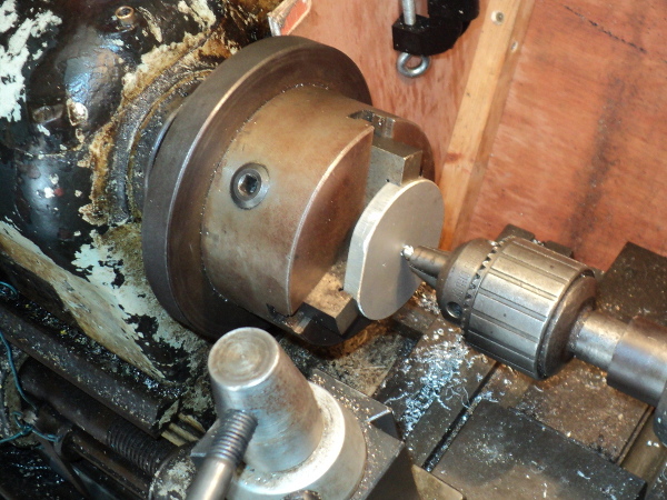
Next step was to skim the last 10mm of the bar down to be a snug fit in the bore of the gudgeon pin itself, as the pin is taper bored this proved a bit fiddly but it was managed.

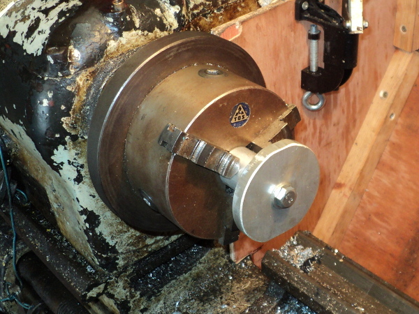
Next was bore a 3mm hole down the middle of the bar, part off the first button to length and then repeat the whole process.

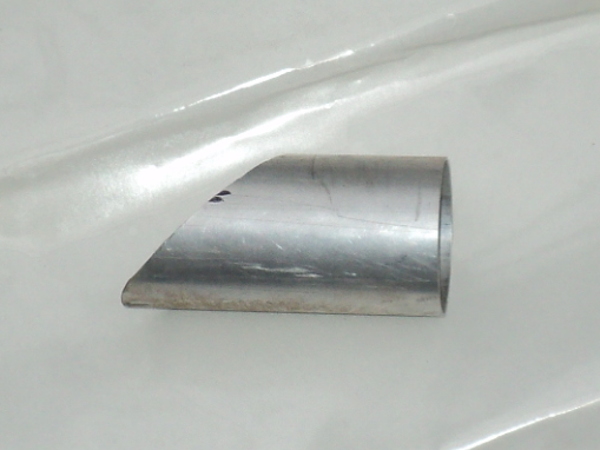
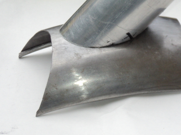
Snag here is that these buttons are flat faced, but they have to go against a round bore. A look on Google gave me the required clearance to skim a shallow taper onto the face so that only the central few mm of the button was able to touch the bore and as they have to run with a slight clearance to the bore, same as the piston skirt, it was a simple job to skim that in.

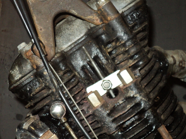
Now the acid test, put the buttons into the pin and try it in the bore, an easy fit with a nice clearance to each side, jobs a good ‘un!, now to build things up again.

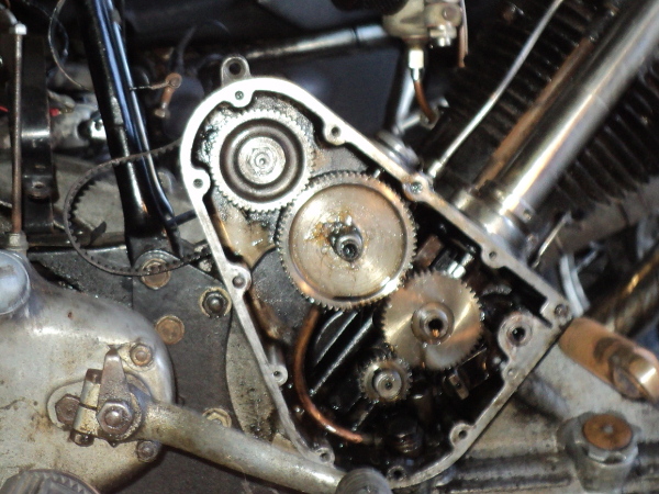
A not uncommon trick with a rebuild is to put the piston into the bore first and then lower it onto the head studs, sliding the gudgeon pin into place and fitting the circlips before sliding the barrel into place.

What isn’t said is that it can be a right fiddle getting the small end eye to line up with the gudgeon pin bores at all as the con-rod keeps trying to fall forward, and then you have to get the match exact enough that the pin will slide home through both the piston and the small end, remember that there is no clearance between these, it needs an exact match. At least there was no trouble with fitting the pin circlips since I was using the buttons.

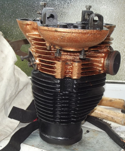
After that it was just put everything back in place, believe it or not the biggest fiddle was replacing the exhausts!.

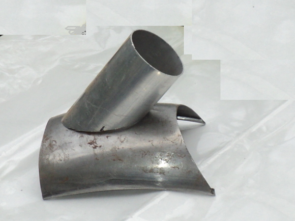
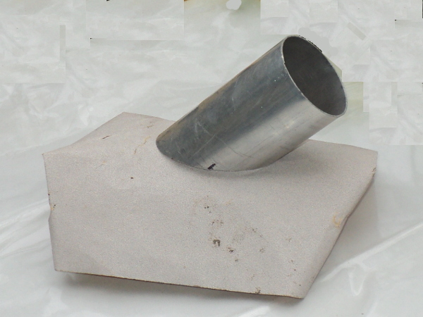
What is needed here is for the flange on the pipe to fit flush against the stub on the head. If you try to put the complete pipe and silencer in place as a unit, the flange will be on a tilt against the stub and you will not be able to pull them flush to using the retaining nut to get a seal, you need to have just the pipe in place and pull up the nut while wangling the pipe around to make sure everything mates up square before rotating it into place and fitting the silencer last, – – – and then you have to repeat on the other side!.

All that’s left to do is fit the carb, then the tank, add some fuel and give her a kick.

Story book ending is to fire up first kick and settle to a steady tick over.

Well second kick the old bitch kicked back and it took another couple of kicks before she was running and the carb needed setting up.

On initial kick over compression was down but after taking a couple of miles run it came up to reasonable and it’ll take a couple of hundred miles to bed the new ring in so all in all I’m happy with the result, just have to see how much oil she’ll be using.

What to do with the rebored M120 barrel? Well I’m considering skimming the spigot down to suit and shortening the barrel, this would have to be done on a mandrel but it is possible, or I could always source another M100 barrel and bore that to suit the Rover piston, it’ll depend on oil consumption once the rings have bedded in.

Getting Bored

The old Panther has been getting a bit greedy lately, in fact it’s been getting so that I needed to top up her oil just about every time I filled her petrol tank.

Now Panthers are known for their thirst for oil but this is a bit extreme, even for one of them and so it was obvious “something needed to be done!”.

One reason given for their thirst is their old fashioned oil ring technology, straight out of the early 1930’s!. Bearing this in mind, as well as the fact that the old girl had been rebuilt onto a worn bore and that I’d put another 4kmiles at least onto that, I decided to try a new bore.

There is a conversion available through the Panther club where you replace the piston with one from a Rover 3.8 car engine, This involves some modification work to be done on the piston but an already modified piston is available through the club, as are all the required gaskets for the job.

It means over-boring the barrel to plus 75thou but there is sufficient “meat” in the barrel to accept this and still be able to take the next oversize! These old girls were well built though, and to last!!.

When I originally rebuilt the old lady there was a choice of barrels to use. The one I selected had the better bore but a broken fin and I used this in preference to the cosmetically better but worse worn barrel so this is the one that has been bored out to suit a club piston.

I had asked for the barrel to be bead blasted before being bored but this was not done so I had to set to with wire brushes on the barrel once I got it back to clean it up for painting.

It was then given 3 coats of black “Smoothrite” from a rattle-can and put out in the glazed porch to harden off in the sun for a week.

Barrel

The barrel resplendent in its new paint

All this could be done before a spanner needed to be set on the old lady herself and that moment had now almost come!.

A decision had to be made as to the cylinder head. This would need to be repainted to match the barrel. It’s a cast iron head so the obvious seemed to be to just black it the same as the barrel. BUT! An option appeared.

Back at the time she was originally built the “go to” option for the more sporting bikes was to have a bronze cylinder head, aluminium alloy technology not yet being up to that job and, knowing that there had been a number of bronze heads cast for Panthers, I could paint the head in bronze!. Decisions! — Decisions!!.

Anyway before I could do the head I had to remove it from the bike so it was out into the garage and start the dismantling work.

As always stripping off the ancillaries takes longer than the actual dismantling but the old lady soon stood with her head stripped off.

Looking into the barrel I could see the piston crown was oily so that explained the high oil usage!.

I tapped the head through-bolts down to level with the top of the barrel and then left her there while I got to work on the cylinder head itself.

A session in the wash tank got the head cleaned of oil and then it was a case of out with the wire brushes to get it down to as near bare metal as I could before painting began.

Also required before paint was applied was to mask off the exhaust stub threads and the joint faces, it’s surprising just how fiddly a job this is!

I went onto ebay and got a tin of a high temperature bronze paint, paint intended for brake callipers and I’ve given the head a couple of coats so now we’ll just have to see how well this paint stands up to the temperatures round the exhaust stubs!, if it come to the worst I’ll just give the head a coat of cylinder black and go back to standard.

Bronze Head Head & Barrel

The cylinder head in bronze and it fitted in place

It looks a bit bright here but it should dull down with a bit of use, otherwise I can add a spot of black to the paint left in the tin to mute it down a bit and give the head a coat of that.

A snag when re-building a Panther engine is that the standard cylinder bore is 87mm. The biggest of the easily available “Terry’s” piston ring clamps however only goes up to 85mm. It can be stretched to cope with 87mm but it won’t cope with the 89mm Rover piston so the usual assembly trick of sliding the barrel onto the piston with the rings in a clamp won’t work, especially since the overboring takes out most of the usual taper lead-in from the barrel base.

This means I’m going to have to assemble the piston into the barrel and then offer the barrel and piston together up to the crankcases, slide the gudgeon pin into place and fit the circlip, what could easily be done on my own has just become a two person job, one to handle the barrel and the other to fit the gudgeon pin!

Anyway the original barrel is now off and I’ve got the crankcase face all cleaned down, I’ll use some Hylomar as a sealant here on re-assembly to try to keep the joint oil-tight.

A Bit More Support.

A downside of using the Panther as a solo is that, being a rigid-framed machine she does not have a centre stand, any time you stop it’s a case of working your way to the back and heaving her up onto the rear stand. While this stand does have a “Roll-On” foot it’s still a hassle.

Unfortunately Panther never supplied a side stand for their machines and because they do not have an underframe it is not possible to fit one of the after-market “clamp-on” universal fit side stands.

However, between the wars there was a stand available that could be used and there is now someone manufacturing these once again.

The stand in question is the “EsWay” and a modern version is available as the “Vintelle”from Mick Hall Engineering in Otley.

CREATOR: gd-jpeg v1.0 (using IJG JPEG v80), quality = 90

1928 Advert for Esway stand

I made contact with him to enquire as to its suitability for an M100 Panther and discovered that his first one had actually been fitted to an M100 so I ordered one up, this was late on on Tuesday so the order would be processed on Wednesday. It was delivered on Thursday morning!

Packed stand kit

The stand came better packed than just about anything else I have bought on-line, putting the standard Ebay and Bangood efforts to shame, along with a comprehensive fitting guide, so it was out to the garage and get on with it.

The stand fits across the rear sub frame, as far forwards as is practical, about level with where a centre stand would fit. It comes with various fittings to suit a wide variety of machines so first thing is to sort out the best ones for your purpose, then a re-read of the fitting instructions before lifting the spanners!.

As the Panther has an exhaust on either side I selected the lower mount with the greatest stand off and assembled it loose onto the lower chain stay and attached the stand to it.

Lower bracket mounted on bottom chain stay

There’s a choice of two upper mounts in the kit so next thing was to see which was needed.

I extended the stand to make sure it would clear the nearside exhaust and made my selection to suit, fitting it round the upper chain stay.

All that was left to do was to snug everything up and make sure the stand foot had clearance and that it was clear of the ground when the bike was laid over into a corner, not a good idea to have it fouling!.

Upper bracket goes onto upper chain stay and stand mounts across the brackets.

The only criticism I have is that the mountings supplied for it are slotted pan-head set screws, I would have preferred to see Allen cap screws or even just simple hex head bolts, a minor niggle when all is said and done.

What’s New?

It’s been a while since I posted anything on this blog, too long! But there’s not been much happening with the bikes as they’ve been running well. However I’m feeling in need of a change now so –.

I’ve taken the sidecar off the big Panther, not the easiest of jobs when working on your own, but do-able, the body is now up on a pair of trestles in the shed and the chassis is in the back yard.

The Panther now stands as a solo in the garage, but she’s not on her own as the old BMW has been brought out of storage and is standing beside her, they make a good pairing, the 600cc 1937 Panther M100 and the 750cc 1940 BMW R12.

Although the Panther has the smaller displacement engine of the two she is the more powerful at 26bhp to the BMW’s 20bhp, but the BMW is a twin cylinder side-valve with a heavy external flywheel so is possibly the better slogger of the two, still neither was intended as a sports bike.

Anyway the BMW is set up with a full set of Steib quick release sidecar fittings so once I have the chair set up for her I can drop it on and off in around five minutes work, useful!!

Now, what does the BMW need doing to get her in commission again?

Well her battery is an AGM sealed unit and has survived her spell in the storage unit. It was still showing about half-charged when I put it on the charger. She is magneto ignition and that’s sparking well but I’ll treat her to a new pair of plugs.

How about oils?, well oil is cheaper than metal so it’s new oil all round, and owing to her age it’s an old-fashioned non-detergent type oil. Equally I needed new drain and filler plug gaskets.

On a machine of this age these should be the hollow rolled-copper type rather than the solid aluminium ones BMW now supply. A quick rake round on ebay soon found a supplier of these in the necessary 14mm and 18mm sizes.

Rather than run her up to hot on the old oil I let her drain out overnight and then it was just a case of fill the engine to between marks on the dip-stick, fill the gearbox and final drive until the oil reached the bottom of the filler hole threads and that was that.

Now the acid test! I put a half-gallon of fuel into the tank, no leaks visible! GOOD!!, turn on the tap (which way is “ON” and which is “RESERVE”??, I can’t remember!! ).

OK, the carbs filled up so a good tickle on each carb, crack open the throttle and turn over the engine several times to prime the cylinders, then it was just switch on the ignition and kick her over.

While she fired she didn’t pick up so a tad more throttle and try again and the old girl was running again! Tick-over balance is a bit off but I’ll need her warmed through to set that up so it will have to wait.

Now I know she’s a runner what else needs doing.

An immediate obvious is indicators!. Last time out she was hauling the chair.

I know it’s non-original, but on modern roads an outfit NEEDS indicators and now you can use LED units without overloading the electrical system so she was fitted up with lights on one side, the others being on the chair. So it’s get another pair of indicators and fit them.

I had to make up (and paint) a set of mounting brackets for them, run in the wiring and then tap it into the circuit to the sidecar indicators, a quick check and they were working..

Next thing was cosmetics, the front mudguard needed some serious touch-up where the paint has been badly scarred and had started lifting while the old lady had been in the storage unit.

Fortunately it can be redone while still on then bike as it would be serious hassle to remove it and then a dose of “T-Cut” after about a fortnight’s curing and then a polish job should see things OK.

As I’m writing this she’s standing in the garage with the first top coat on the guard giving it time to harden off before she’s put away for the night, another coat tomorrow should then see it ok.

I can’t really complain as both guards were in a bad state when I got the bike back at the beginning of the Eighties and they needed serious patching to be made usable, and she has seen some serious mileage since then!

= = = = = = = = = = = = = = = = =

When I had a look at things the next day I was very happy as to the finish, the “Craftsman” paint I was trying out as a replacement for my old favourite “Tekaloid” came through with flying colours.

Only trouble was the contrast with the old paint, this had weathered over time so the new paint stood out like the proverbial on a barn door!.

So I broke out the “T-Cut” and gave the guard a good rub down and that did the trick, you no longer noticed the repair unless you looked closely, snag is I now have to do the rest of the bike to get it to match the front mudguard!.

The R12 is quite heavily pinstriped so this repair has left a gap in the lining on the front guard that I’ll need to patch, so I now need to break out the lining brushes.

Lining is properly done free-hand and the difficult bit is getting a tight curve without smearing. My way round this is to mask out the line so that any smear goes onto the masking tape, problem is that with the BMW double line I’ll need to do one line and let it harden off before I can mask off to do the other.

I’ve also had the old girl out on the road for a run to see how things were.

I found that while she was willing to start and run, the start-up from cold was not as willing as it used to be and she was very reluctant to start from hot.

What I’ve done today is to treat her to a pair of new plugs, the old ones had been in for a long time now. I’ve also had the carburetters off and stripped and cleaned them, they have been standing for a couple of years and what fuel had been left in them had dried out and left a “varnish” of crud inside the passages and jets.

Fortunately she’s running on a pair Amal 276’s and these are an easy carb to strip down and clean.

I’ll need to synchronise the slide opening before I take her out again and while that’s a fiddly job it’s not that difficult.

I’ve also offered up the sidecar chassis to the bike, before I actually fit it I’m wanting to rig a sidecar brake. I had a sidecar brake on the Panther outfit and found it useful, after all the bikes brakes are from the 1930’s and brake technology has come a fair way since then so every little helps.

The rear brake on the R12 is with a heel operated pedal on the right-hand side. What I’m doing is to mount a pedal onto the sidecar chassis with a lever coming straight across to the bike and level with the rear brake pedal so its pad lies alongside the bike’s one. This means that when I apply the bike’s brake I’ll also apply the sidecar brake as well, and by rocking my foot I can vary their relative pressures.

However I’ll also be able to apply either brake on its own to give differential braking which can be useful to assist in cornering.

Only thing is that while I’ve the brake pedal set up I’ve still to arrange the cable fitment at the drum end of the system, as a “By The Way” the chassis I’m using is from an LS200 Steib. The wheel us from a Ural/Dneiper, a half width hub that looks in keeping with the R12 and the brake mechanism is an Enfield type from a rigid-framed Panther.

Lights On – Again

Now that I’ve taken the sidecar off the Panther I can again ride her as a solo.

First time out felt a bit strange, probably because it’s been on sidecar for a while and the tyres will have worn to suit a sidecar outfit.

Since it’s only been for around 1500 miles they’ll soon wear back to suit a solo so that’s no real problem, especially as she will not be used as a performance machine.

Once I got back home I realised that the headlamp was not working, in fact none of the electrics were!.

First thoughts were that I’d managed to blow the main fuse but a quick look showed that this was not so, and then I saw that the stop light was still working.

This showed that the battery was still charged and its connections were sound.

But the stop-light is not fed from the headlamp area, it has its own feed from the battery, so suspicion fell onto the wiring and it was out with the multimeter.

The wiring system on this old lady is laughably simple when compared with that on a modern machine.

There is a wire runs between the battery and the ammeter.

Another wire runs between the regulator and the main switch.

One runs from the switch back to feed the rear light and then I’ve added an extra one from the headlamp shell to the frame ground point and that’s the main fore and aft loom!.

There is in addition a connection between the ammeter and the main switch and then there’s the wiring going to the headlamp itself plus that to the speedometer bulbs and to the horn.

The headlamp is normally grounded through the frame of the bike but since I had added a grounding wire as a back-up, suspicion was on the battery lead to ammeter wire.

I used the multimeter to test between the ammeter and the headlamp shell and sure enough there was no power showing.

Suspect point was where the loom flexes as it exits from under the fuel tank and crosses to the headlamp shell.

Normally there would be only a small amount of movement here but I’ve had a sidecar fitted, this means that as with a sidecar fitted you actually steer by turning the bars there is much more movement, and hence flexing of the loom here.

Sure enough, I could feel a break in one of the wires here and so decided to splice in a new section of wire.

This meant taking the tank off to get access, so it had to be drained!, typically I’d just tanked up, luckily only to half-full!.

I opened up the loom at the break to find the wire had totally parted and so I pulled that wire out of the loom further back to under the tank to make a splice.

Until now I’d assumed it was the main battery feed wire forward had parted but it turned out to be the additional grounding wire I’d added! Shows how unreliable a frame ground can be!.

To be safe I checked by running a temporary ground wire from the headlamp to battery ground and – Lo and Behold everything worked!.

This made life much easier as the ground point inside the headlamp is much simpler to reach than the power point!.

Rather than just bridging the break I ran the new wire from the splice point under the tank direct to the headlamp ground, this meant I only had the one splice in the wire, less potential for problems!.

A swift check of the system again and everything was working so it was just putting things back together, add fuel and we were back on the road.

What’s Happening??


It’s been a while since I posted anything on this blog, too long! But there’s not been much happening with the bikes as they’ve been running well. However I’m feeling in need of a change now so–.

I took the sidecar off the big Panther a couple of days ago, not the easiest of jobs when working on your own, but do-able, the body is now up on a pair of trestles in the shed and the chassis is in the back yard.

The Panther now stands as a solo in the garage, but she’s not on her own as the old BMW has been brought out of storage and is standing beside her. They make a good pairing, the 600cc 1937 Panther M100 and the 750cc 1940 BMW R12.

Although the Panther has the smaller displacement engine of the two she is the more powerful at 26bhp to the BMW’s 20bhp, but the BMW is a twin cylinder side-valve with a heavy external flywheel so is possibly the better slogger of the two, still neither was intended as a sports bike.

Anyway the BMW is set up with a full set of Steib quick release sidecar fittings so once I have the chair set up for her I can drop it on and off in around five minutes work, Useful!!

Now, what does the BMW need doing to get her in commission again?

Well her battery is an AGM sealed unit and has survived her laying up, still showing about half-charged when I put it on the charger. She is magneto ignition and that’s sparking well but I’ll treat her to a new pair of plugs.

How about oils?, well oil is cheaper than metal so it’s new oil all round, and owing to her age it’s an old-fashioned non-detergent type oil. Equally I needed new drain and filler plug gaskets.

On a machine of this age these should be the hollow rolled-copper type rather than the solid aluminium ones BMW now supply. A quick rake round on ebay soon found a supplier of these in the neccessary 14mm and 18mm sizes.

Rather than run her up to hot on the old oil I let her drain out overnight and then it was just a case of fill the engine to between marks on the dip-stick and the gearbox and final drive until the oil reached the bottom of the filler hole threads.

Now came the acid test, she’d been stored with a dry tank so I put a half-gallon of fuel into the tank, no leaks visible! GOOD!!, turn on the tap (which way is “ON” and which is “RESERVE”??, I can’t remember!! ).

OK, the carbs had filled so a good tickle on each carb, crack open the throttle and turn over the engine several times to prime the cylinders, then it was just switch on the ignition and kick her over.

While she fired she didn’t pick up so a tad more throttle, try again and the old girl was running again! Tick-over balance is a bit off but I’ll need her warmed through to set that up so it will have to wait.

Now I know she’s a runner what else needs doing.

An immediate obvious is indicators!. Last time out she was hauling the chair.

I know it’s non-original but on modern roads an outfit NEEDS indicators and now you can use LED units without overloading the electrical system so she was fitted up with lights on one side, the others being on the chair. So it was get another pair of indicators and fit them.

I had to make up (and paint) a set of mounting brackets for them, run in the wiring and then tap it into the circuit to the sidecar indicators, a quick check and found they were working.

Next thing was cosmetics, the front mudguard needed some serious touch-up where the paint had been badly scarred and had started lifting while the old lady had been sitting in the storage unit.

Fortunately it can be redone while still on the bike as it would be serious hassle to remove it and then given a dose of “T-Cut” after about a fortnight’s curing followed by a polish job should see things OK.

As I’m writing this she’s standing in the garage with the first top coat on the guard giving it time to harden off before she’s put away for the night, another coat tomorrow should then see it ok.

I can’t really complain as both guards were in a bad state when I got the bike back at the beginning of the Eighties and they needed serious patching to be made usable, since then she has seen some serious mileage!

A Little Light

With the sidecar fitted and aligned, before I can take it out on the road it needs lights to be legal.

With it being a 1937 machine I just need to show “a white light to the front and a red light to the rear”, after all at that time gas lighting was still common, but as this outfit is to be used on modern roads I need to be a  bit more practical.

What I am fitting is a spotlight set up as a Daylight Riding Light, a white front running light, a red rear running light, a stop light and indicators.

Indicators are totally out of period but in modern traffic on a sidecar outfit they are “A DAMN Good Idea!”.

I had a pair of the Hella round indicator/running lights in stock so these became the basis of my lights.

As the wheel and mudguard (fender) are on the outside edge of the outfit the lights need to mount onto this but as the guard is semi-circular this gives a problem, the Hella units are intended to fit onto a flat, vertical surface and the guard has a compound curve, at the point where the lights need to mount there is a 45° slope to the vertical.

First thing was to make the mounts for the lights. These need to fit onto the guard and give a suitable surface to mount the lights.

As the lights are 75mm in diameter I took a 6 inch length of 75mm OD alloy tube with a 1.5mm wall thickness and cut it into two lengths on a 45°angle.

Mount tube

The sawcut alloy tube

These, when mounted onto the guard will fit onto the guard part way up it and give the necessary vertical surface, unfortunately though the plain cut end does not match the curves of the guard.

tube onguard

Showing mismatch between tube and mudguard, it only touches at the ends

However from fitting the guard onto the sidecar I had a short length of it spare

spare guard

“Spare” length of mudguard

so I took this, fixed some 80 grit abrasive sheet to it.

I next took a black marker, used it to “black up” the cut end of the  tube

tube end blacked

“Blacked-up” end of tube

and then started rubbing the mount on the abrasive sheet.

rubbing in

Rubbing in end of tube to match mudguard

This gave me “witness marks” showing where the guard was contacting the mount and so, where the mount needed trimming back.

witness marks

Rubbed end of tube showing “witness marks” where material still has to be removed

This was done using a Dremel tool and a sanding drum.

Repeated re-blacking, trials and trimming gave me a pair of mounts that were a reasonable fit onto the guard and which, given some rubber beading, would make a sound joint against it.

finished job

Tube matched to contour of mudguard

I now needed bases for the lights themselves. To make these I took a pair of 10mm thick alloy disks of about 85mm OD.

These were each chucked up in the lathe

raw disk

Raw disk in lathe chuck

and had a central 8mm hole drilled through.

After this they were removed from the chuck their place was taken by a short length of 32mm OD bar. This had its end faced flat and then had a central hole drilled into it. This was tapped to take an 8mm bolt.

centrebdrilled

Disk centre drilled 8mm

This gave me a mandrel to work the disk on and so one of the disks was bolted to it, this meant that I could now turn the disk about it’s centre and it was able to have the edge turned down to size.

on mandrel

Disk mounted on mandrel for turning

This disk was now skimmed down to 75mm diameter, the same as the OD of the tube.

Next step was to turn a 4mm deep spigot on the disk to make a tight fit in the tube.

I then reversed the disk on the mandrel and another 4mm deep spigot turned on the other side, this time sized to mount the Hella lens onto.

finished turned disk

Disk turned to size and lens fitted

Suitable mounting holes were drilled and tapped into the alloy to take the lens mounting screws.

All that was now needed was to supply light to the lenses and rather than use incandescent  bulbs I opted to use LED lights instead.

Going onto Ebay, I ordered up 4 amber, two red and two white LED marker lights. These mount with a 10mm stud on their backs.

As these are the equivalent of a 10 watt bulb the intention was to use two amber LEDs to supply each indicator,one white for the front running light and two reds for the stop light.

Going to the disks, I marked off the horizontal diameter through the lens mounting screws and drilled a pair of 10mm clearance holes above it. One one disk I then drilled a single 10mm clearance hole below the centre line and on the other a pair below the line.

drillee disk + LEDs

Front unit disk fitted with LEDs

Mounting two of the amber LED’s above the line gave me my indicators and the fitting the whites or reds below gave me my front running light and my stop light.

I needed a rear running light as well and so a similar but smaller unit was made up using a 50mm diameter LED rear marker light to supply the lens.

All that was left to do was give the mounts a lick of paint, mount them onto the guard via the central hole in the disks and to run in the wiring.

Finished job

The completed light unit in place


Lining it up

It’s now time to start fitting the sidecar. I’ve not yet refitted the tank after the dynamo belt drive conversion so now is an ideal time to do this.

First thing is to get the chassis connected up to the bikes frame.

The chassis was laid out alongside the bike and put up on blocks.

The front swan-neck was put in position on the bike and loosely clamped to the sidecar chassis, as was the rear ball joint fitting.

Fitting a sidecar has been described as a black art, well now starts the black magic!

First thing to set is the lead, the sidecar wheel has to be set a bit in front of the bikes rear one, how much depends on the type of sidecar, the intended use and the bike itself.

A bike with rear suspension needs more lead than a rigid bike; with a heavy sidecar you needs less lead, with a light sports chair you need more. This all boils down to the answer to “How Much?”  being “It Depends” but it is not critical to a fraction of an inch, I’m starting with 6 inches of lead on a light sports sidecar and this can be adjusted, if needs be, after road test. On my later outfit, which does have rear springing, I’m running with 10 inches lead on a similar sidecar.

So the chassis was slid around on the blocks till I had the appropriate lead and the fitting clamps tightened a bit.

setting up

Lead and level have been set, now it’s the toe-in to do. Notice the two “fine alignment tools” by the front wheel

The chassis was now able to have the support blocks removed and, as the bike was now standing on her wheels as well, it was time to level the chassis.

Working with a rigid bike here it was set level side to side, when the bike has rear suspension you’ll need to have the bike loaded when setting this.

While you want the sidecar level side to side, going fore and aft you want it nose high, even when loaded, so the chassis needs setting with the nose rail between a half inch and an inch higher than the axle rail. Getting these right can be a bit fiddly as with the chassis I am using, adjusting the side to side level will also alter the lead if your not on top of the job.

Now comes the most important of the settings, the toe-in.

With a sidecar outfit, the power is all on the bike side, the sidecar wheel is unpowered.

This means that when running straight the sidecar wheel always drags a bit and tends to pull the bike towards it. It is not a heavy pull but it does get tiring compensating for it all the time, so the trick is to set the sidecar wheel to steer a little the other way by pointing it in towards the bike, to “toe it in”.

Thing is “By how much?” and the answer is “It all depends!”. This is the big variable and depends on the bike, the roads you use, road camber will affect it, how fast you are going etc. so you have to compromise and then make adjustments to suit.

Experience leads me to use an initial setting of around 3/4 of an inch over the length of the bike so a straight edge (here a length of 4 x 2 timber) is laid against the bikes wheels, I have the same size tyres fitted fore and aft so it’s set up on blocks and adjusted so as to touch evenly at four points across the wheels.

Similarly another straight edge is laid against the sidecar wheel, touching evenly against it and the distance between the two straight edges measured, first just behind the rear wheel and then just in front of the front one, the difference between the measurements giving the amount of toe-in.

This is adjusted to suit at the chassis clamps, the sidecar wheel being lifted off the ground and replaced and the straight edges reset before a check measurement is taken so as to remove any tyre distortion from the figure.

Once I had the required toe-in the two main sidecar clamps could be tightened up but this is another setting that will probably be modified after road test.

This left me with the sidecar lean out to set. The bike needs to lean a little way out from the sidecar. With a left-hand sidecar in UK you want the bike to be a little past vertical to allow for the road camber, so you drop a plumb line from the handlebar end and set the lean to around a half inch.

setting lean-out

To set the lean-out drop a plumb line from the handlebar.

I’ve got a right-hand sidecar however and any lean I set will be added to by the camber, if I set too much lean I’m going to feel the bike leaning over, so initially I’m setting so as to have the bike vertical on a level surface so on the road the camber will be giving the lean out.

This is set using the rear upper brace, that one goes to just below the saddle.

setting lean-out

Lean -out is set using the rear brace that goes to under the seat

That’s the main adjustments made and locked by tightening the chassis clamps. Some people will tell you these three fittings are all you need but a fourth one is definitely desirable, without it you can feel the outfit flexing in corners, not only that but the toe-in varies as the outfit flexes, Not Ideal!.

This fitting goes across between the front of the sidecar chassis and a low point on the bike to triangulate the swan neck. Normally you would take it off the front engine plates but a Panther does not have these.

However P&M supplied a mounting point on the engine right beside where the front engine supports are so its taken to there. All you do is adjust the fitting so that the clevis bolts slide easily into place and then lock it up in that position.

adding the body

The lower front brace goes between the front of the chassis and the bike.
Once it is in place then the body can be fitted.

With the basic settings made it now requires a road test to determine what adjustments need to be made to these.

What to expect is that as you pull away there will be a small degree of low speed steering wobble that disappears as soon as you are moving. This is normal and you soon do not even notice it, you don’t after all on your car and it does the same. You can reduce this with a steering damper, but too heavy a damper makes for heavy steering, careful attention to the setting up will minimise it, a better remedy.

Now try some slow turns, towards and away from the sidecar, ideally the effort should be about the same but if turning towards the chair is noticeably heavy then you need to reduce the lead to stop the wheel crabbing. But too little lead affects stability and makes the sidecar wheel more prone to lifting.

Does the outfit run straight under steady power? The ideal is to be able to hold it steady with one finger on the bars, does it pull to one side or the other? This is a pointer to the toe-in setting, pulling all the time towards the sidecar — increase the toe-in, pulling away from it — decrease the toe-in.

Open the gas and as you speed up you should pull a little round towards the sidecar; now shut the gas,as the bike slows on engine braking you should feel the sidecar pull round towards the bike.

If at steady speed you can feel it is pulling only slightly but enough to need constant input to stay straight then a SMALL adjustment to the lean-out can help but don’t overdo it, look on this as a final fine trim to getting the toe-in right.

So far all your tests should have been below 30mph, now it’s time to speed up a bit.

Take it gently and try at higher speeds, it may need a bit more fine tuning to get the outfit handling “Just So” but it’s well worth the effort as with a well set up outfit out on the open road it steers largely on the throttle, needing very little input to the bars.

Complete outfit

Final Result, ready for the road

Timing It.

Having removed the magneto and with replacing the drive dog on it with the POC’s uprated version I needed to retime the ignition.

On a Panther there are no external timing marks and the ignition point is normally quoted as with the magneto set on full advance at a set distance before TDC,‭ ‬measured with a rod down the spark plug hole in the head.

An option is to set it to TDC with the magneto on full retard,‭ ‬determined the same way.‭ ‬This sounds easy but it is in fact not so simple or accurate to determine because there is an appreciable amount of crankshaft rotation at TDC with minimal piston motion and it is easy to be a fair bit out.

I decided to make up a special tool for this.

The obvious way is just to take an old plug,‭ ‬smash out the ceramic and use a rod going down through it.

Downside with this is that the rod is going into the cylinder at an angle so that any distance measured on it will not be an accurate measure of piston movement,‭ ‬not only that but because it is at an angle it can jam the piston rather than being pushed up by it and cause damage.

I’ve a spare cylinder head and using this I found that not only could an old spoke go down the plug hole vertically when angled across it but there was a flat horizontal face on the outside of the head at the plug hole to set the tool on and also act as an index point.

Spare head

Head showing flat area at plug hole

So I took a piece of‭ ‬2.0mm flat aluminium sheet scrap and cut it to fit across this flat area.

I then drilled a‭ ‬5/16inch‭ (‬8mm for the metrically inclined‭) ‬hole in the plate,‭ ‬centred on the plug hole and filed the bottom edge of the plate below that to a chisel edge.

Alloy plate

Alloy plate

As I wanted to keep the spoke vertical I scribed a line up through the hole centre and using the corner of a hand file I cut a‭ “‬V‭” ‬groove on it.

The spoke will be pulled into this groove and so locked at‭ ‬90°‭ ‬to the edge of the plate.

Next I took a length of studding and then drilled across it’s diameter close to the end,‭ ‬the drilling being just clearance for a spoke and an inch length cut off the studding.

Cross drilling studding

Component parts of tool

Component parts of tool

The spoke was then put through the hole,‭ ‬the cut studding put through the plate so that the chisel edge was against the spoke and a nut and washer fitted so that while the spoke was held against the plate it could still be pushed up and down through the bolt.

Assembled tool

Assembled tool

The plate was then put in place on the cylinder head with the spoke going down the plughole and the bottom edge of the plate was held firmly down onto the flat face above the plug hole.

The motor was then gently turned over and as the piston rose up the bore it pushed the spoke up through the bolt.

Tool in use

Tool in use

Since the bolt had been tightened enough to hold the spoke but not enough lock it in position,‭ ‬as the‭  ‬piston went across TDC and back down the bore on the other side,‭ ‬the spoke was left at the TDC position.

The device was removed from the head and a mark was put on the spoke at the chisel edge.

Reference was made to the bikes manual in the POC websites‭ “‬Library‭” ‬to find the correct advance distance for my motor,‭ ‬45°‭ ‬or‭ ‬19/32‭”‬,‭ ‬and another mark made on the spoke at that distance above the TDC mark.

‭(‬If you are making up one of these be careful to check what the correct figure is for your bike,‭ ‬official figure varies by some‭ ‬10°‭ ‬according to the year of the bike.‭)

This mark was aligned against the chisel edge on the plate and the nut tightened down to lock the spoke in place.

The motor was now brought to TDC on the compression stroke and then turned backwards to take the piston back down the bore to before the ignition point,‭ ‬the new tool put in place with the spoke end down through the plug hole and the motor gently turned forwards until the piston was felt to touch against the end of the spoke.

The motor was now at the correct spot to set the magneto timing at full advance so the Magneto could now be set in place and its timing set.

This is a bit more sophisticated than the old idea of using a‭ “‬pencil down the plug-hole‭” ‬but it’s easier to use when set up,‭ ‬it has a clearer index point AND there’s no chance of losing it down the plug-hole.

This new tool is small enough to keep in the tool-set carried on the bike itself, I’ve got an old tobacco‭ tin with the tappet spanners, push-rod tube spanner, mag spanners, a set of feelers, a packet of cigarette papers and now this tool kept in the toolbox, ‬after all,‭ ‬if you have it with you then you won’t need it but if you haven’t got it you will‭!

timing gears

Belt Up‭ (‬Part Two‭)

As the old lady was being laid up for the winter the chance was taken to drain and remove the fuel tank,‭ ‬this was rinsed out to remove any accumulated crap from across the season and the tank stored on a shelf out of the way.‭ ‬With the modern petrol brews having a limited shelf life it’s no longer a good idea to leave the tank full over the winter.

The carburetter was also drained so that the fuel in it could not evaporate and leave a varnish of additives choking the pilot jets.‭ (‬I was caught out by this last winter with the Velo and wound up having to put her carb in an ultrasonic cleaner to clear it out‭!‬.‭)

Next was to remove the magneto and dynamo and shelve these also for now.‭

This had cleared the decks so next step was to remove the timing cover.

timing gears

Open Timing Case

The joint was initially just cracked open so as to drain the oil and then the cover was removed,‭ ‬forgetting of course to catch the oil pumps pressure pad and spring as they dropped into the drained oil‭!‬.

Having fished them out of the drain pan they were wiped clean and put to one side and I found that unlike on the later motors,‭ ‬the magneto timing gear on my bike is not drilled and tapped to take a puller,‭ ‬it needs a claw type puller‭ ‬and, with the one I have, the legs foul against the timing case wall and prevent it getting a straight pull on the gear.

However on the older Panthers, such as this one, rather than the outer drive disc and the shaft being in one piece the shaft has a separate drive disc on one end and the timing gear on the other.

This meant that I could pull the drive disc from outside the timing case where there is easy access for the puller so it was just a case of unscrew the retaining nut and pull the disc.

Chainwheel

Old Type Chainwheel, notice amount of wear!

Intention was to fit the puller and apply sufficient tension on it to hold things in place before the disc was heated with a gas torch.

Idea was to get the disc to expand a bit and then apply pressure before the heat was conducted to the shaft and expanded that as well, so it has to be done quickly.

Problem appeared in that the moment the puller screw was put in place and before any real pressure was put onto it, the threaded end of the shaft split in two! BUGGER!! Turns out that this is a not unknown problem on these motors, the shaft end being over hardened in manufacture.

Broken shaft

Shaft showing broken end

So I set to and turned up a pressure bushing on the lathe to press against the shaft end rather than the thread end.

Anyway, that worked, the disc was successfully removed and the shaft and gear could be removed from the timing case.

Next step was to replace the shaft with the converted one from the spare motor, only to find that it did not fit!. It seems that P&M increased the shaft diameter across the war years, TYPICAL!.

differing shafts

Two differing shaft diameters

Not only that but they altered the pressure angle of the gears so they are not interchangeable either.

This meant that I had to repair the damaged shaft, not so easy since it was through-hardened.

So the 4-jaw chuck was put onto the lathe and copper shoes put onto the jaws so as not to mark the shaft’s bearing surface.

shaft in chuk

Broken shaft in lathe-chuck

Using the 4-jaw meant that I could set the shaft to run dead true which was accordingly done and the broken end trued off.

The shaft itself was already centre drilled so it was just a case of opening the bore up to the appropriate tapping size.

Since the shaft was a hard steel I used a cobalt stub drill for this job, a cobalt drill will tackle far harder steels than an ordinary jobber drill will,  but their about three times the price!!

Then it was just a case of carefully tapping out the hole to take a bolt and the job was done.

I then had to transfer the alloy pulley over from the other shaft flange and I could then refit the shaft.

The shaft was then put in place in the timing case and the timing drive re-assembled.

The oil pump gear has a pressure pad and spring to hold it in place, this was stuck onto the centre of the gear with a blob of grease before fitting the outer cover.

Pressure pad in place before fitting the outer cover

Pressure pad in place before fitting the outer cover

On going to refit the magneto I ran into another two problems.

The first was that the new pulley masked the drive dogs on the bike side coupling.

Coupling

New pulley masks coupling

To get round this the magneto had to be put onto its platform at the rear of the cylinder so that its coupling could be slid into mesh with the other one, BUT the studs that secure the magneto in place fouled the base plate of the magneto and prevented it from sitting down onto the platform.

Simple, you just remove the studs, put the magneto in place and refit the studs through the base plate! If only it were that easy!

P&M in their ineffable wisdom had chosen to use studs with an enlarged collar in the middle. This collar sits down into a counter-bore in the platform so it does not normally interfere with the magneto’s base, but this collar will not go through the mount slots on that base, equally the studs are threaded 1/4 Whitworth on one end and 1/4 Cycle on the other.

Short time remedy is to replace them with 1/4 Whitworth set bolts until I can source some double-enders but its not ideal as a Whitworth thread is more prone to backing off than the finer Cycle is.

While I had the magneto off I took the chance to replace the drive dog with the clubs easy adjust version and herein lay the other problem!.

The drive dogs on my bike, and apparently those on the later models using the “spider” type coupling, are 5/8 inch wide but the dogs on the clubs unit are only 1/2 inch wide, since my bike is among the first to use the enclosed valve motor, it looks like earlier models used a smaller size drive dogs.

Now it was just a case of fitting the magneto and re-timing the ignition.

Before fitting the magneto the endless drive belt for the dynamo had to be put in place, you can’t fit it afterwards, as I discovered!.

New drive

New dynamo drive

Then it was just a case of fitting the dynamo itself, tensioning the belt and refitting the drive cover. Once the cover is back in position the upgrade is invisible.

Dynamo installed

Dynamo installed

Cover intalled

With cover installed no change is visible