
As the old lady was being laid up for the winter the chance was taken to drain and remove the fuel tank, this was rinsed out to remove any accumulated crap from across the season and the tank stored on a shelf out of the way. With the modern petrol brews having a limited shelf life it’s no longer a good idea to leave the tank full over the winter.
The carburetter was also drained so that the fuel in it could not evaporate and leave a varnish of additives choking the pilot jets. (I was caught out by this last winter with the Velo and wound up having to put her carb in an ultrasonic cleaner to clear it out!.)
Next was to remove the magneto and dynamo and shelve these also for now.
This had cleared the decks so next step was to remove the timing cover.
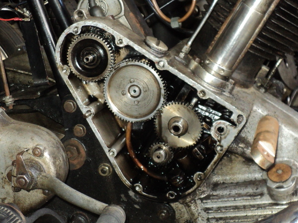
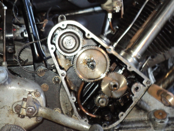
Open Timing Case
The joint was initially just cracked open so as to drain the oil and then the cover was removed, forgetting of course to catch the oil pumps pressure pad and spring as they dropped into the drained oil!.
Having fished them out of the drain pan they were wiped clean and put to one side and I found that unlike on the later motors, the magneto timing gear on my bike is not drilled and tapped to take a puller, it needs a claw type puller and, with the one I have, the legs foul against the timing case wall and prevent it getting a straight pull on the gear.
However on the older Panthers, such as this one, rather than the outer drive disc and the shaft being in one piece the shaft has a separate drive disc on one end and the timing gear on the other.
This meant that I could pull the drive disc from outside the timing case where there is easy access for the puller so it was just a case of unscrew the retaining nut and pull the disc.
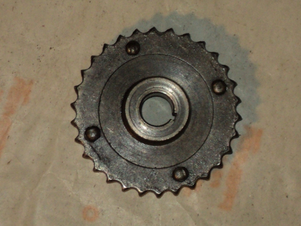
Old Type Chainwheel, notice amount of wear!
Intention was to fit the puller and apply sufficient tension on it to hold things in place before the disc was heated with a gas torch.
Idea was to get the disc to expand a bit and then apply pressure before the heat was conducted to the shaft and expanded that as well, so it has to be done quickly.
Problem appeared in that the moment the puller screw was put in place and before any real pressure was put onto it, the threaded end of the shaft split in two! BUGGER!! Turns out that this is a not unknown problem on these motors, the shaft end being over hardened in manufacture.
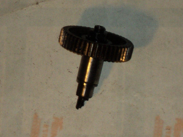
Shaft showing broken end
So I set to and turned up a pressure bushing on the lathe to press against the shaft end rather than the thread end.
Anyway, that worked, the disc was successfully removed and the shaft and gear could be removed from the timing case.
Next step was to replace the shaft with the converted one from the spare motor, only to find that it did not fit!. It seems that P&M increased the shaft diameter across the war years, TYPICAL!.
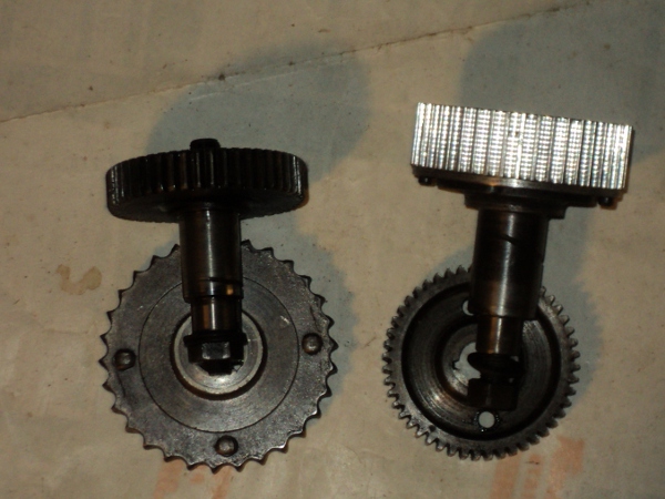
Two differing shaft diameters
Not only that but they altered the pressure angle of the gears so they are not interchangeable either.
This meant that I had to repair the damaged shaft, not so easy since it was through-hardened.
So the 4-jaw chuck was put onto the lathe and copper shoes put onto the jaws so as not to mark the shaft’s bearing surface.
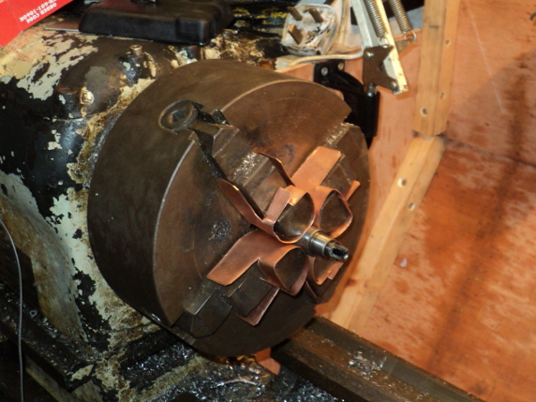
Broken shaft in lathe-chuck
Using the 4-jaw meant that I could set the shaft to run dead true which was accordingly done and the broken end trued off.
The shaft itself was already centre drilled so it was just a case of opening the bore up to the appropriate tapping size.
Since the shaft was a hard steel I used a cobalt stub drill for this job, a cobalt drill will tackle far harder steels than an ordinary jobber drill will, but their about three times the price!!
Then it was just a case of carefully tapping out the hole to take a bolt and the job was done.
I then had to transfer the alloy pulley over from the other shaft flange and I could then refit the shaft.
The shaft was then put in place in the timing case and the timing drive re-assembled.
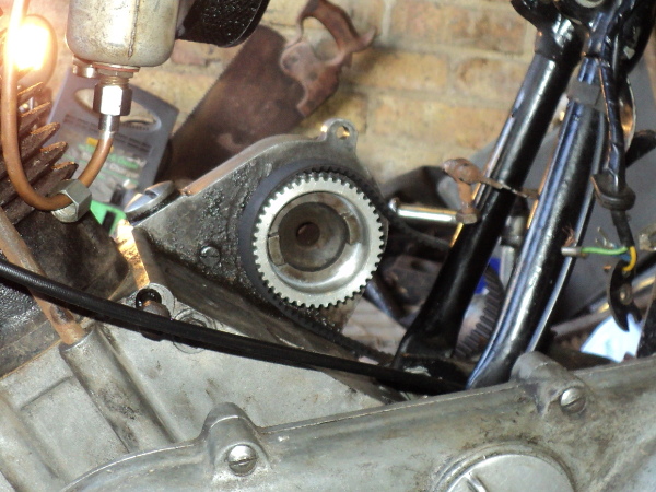
The oil pump gear has a pressure pad and spring to hold it in place, this was stuck onto the centre of the gear with a blob of grease before fitting the outer cover.
Pressure pad in place before fitting the outer cover
On going to refit the magneto I ran into another two problems.
The first was that the new pulley masked the drive dogs on the bike side coupling.
New pulley masks coupling
To get round this the magneto had to be put onto its platform at the rear of the cylinder so that its coupling could be slid into mesh with the other one, BUT the studs that secure the magneto in place fouled the base plate of the magneto and prevented it from sitting down onto the platform.
Simple, you just remove the studs, put the magneto in place and refit the studs through the base plate! If only it were that easy!
P&M in their ineffable wisdom had chosen to use studs with an enlarged collar in the middle. This collar sits down into a counter-bore in the platform so it does not normally interfere with the magneto’s base, but this collar will not go through the mount slots on that base, equally the studs are threaded 1/4 Whitworth on one end and 1/4 Cycle on the other.
Short time remedy is to replace them with 1/4 Whitworth set bolts until I can source some double-enders but its not ideal as a Whitworth thread is more prone to backing off than the finer Cycle is.
While I had the magneto off I took the chance to replace the drive dog with the clubs easy adjust version and herein lay the other problem!.
The drive dogs on my bike, and apparently those on the later models using the “spider” type coupling, are 5/8 inch wide but the dogs on the clubs unit are only 1/2 inch wide, since my bike is among the first to use the enclosed valve motor, it looks like earlier models used a smaller size drive dogs.
Now it was just a case of fitting the magneto and re-timing the ignition.
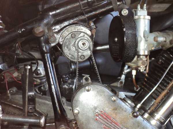
Before fitting the magneto the endless drive belt for the dynamo had to be put in place, you can’t fit it afterwards, as I discovered!.
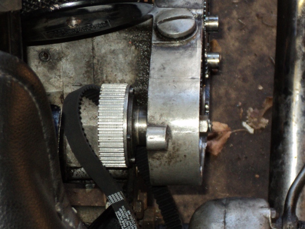
New dynamo drive
Then it was just a case of fitting the dynamo itself, tensioning the belt and refitting the drive cover. Once the cover is back in position the upgrade is invisible.
Dynamo installed
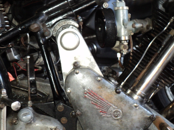
With cover installed no change is visible