
With the sidecar fitted and aligned, before I can take it out on the road it needs lights to be legal.
With it being a 1937 machine I just need to show “a white light to the front and a red light to the rear”, after all at that time gas lighting was still common, but as this outfit is to be used on modern roads I need to be a bit more practical.
What I am fitting is a spotlight set up as a Daylight Riding Light, a white front running light, a red rear running light, a stop light and indicators.
Indicators are totally out of period but in modern traffic on a sidecar outfit they are “A DAMN Good Idea!”.
I had a pair of the Hella round indicator/running lights in stock so these became the basis of my lights.
As the wheel and mudguard (fender) are on the outside edge of the outfit the lights need to mount onto this but as the guard is semi-circular this gives a problem, the Hella units are intended to fit onto a flat, vertical surface and the guard has a compound curve, at the point where the lights need to mount there is a 45° slope to the vertical.
First thing was to make the mounts for the lights. These need to fit onto the guard and give a suitable surface to mount the lights.
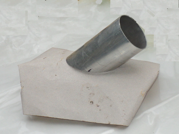
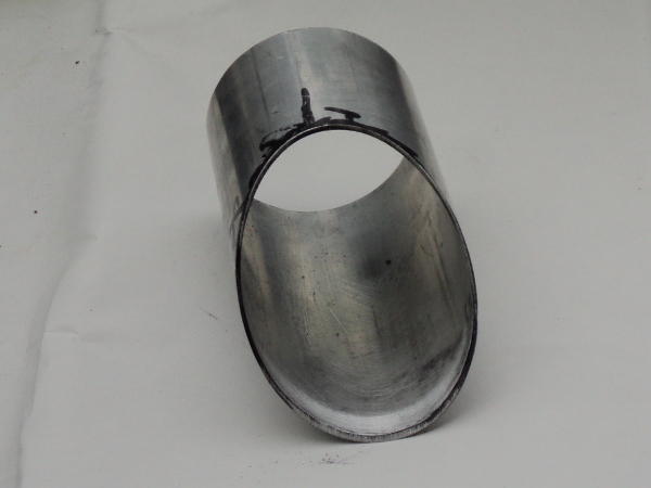
As the lights are 75mm in diameter I took a 6 inch length of 75mm OD alloy tube with a 1.5mm wall thickness and cut it into two lengths on a 45°angle.
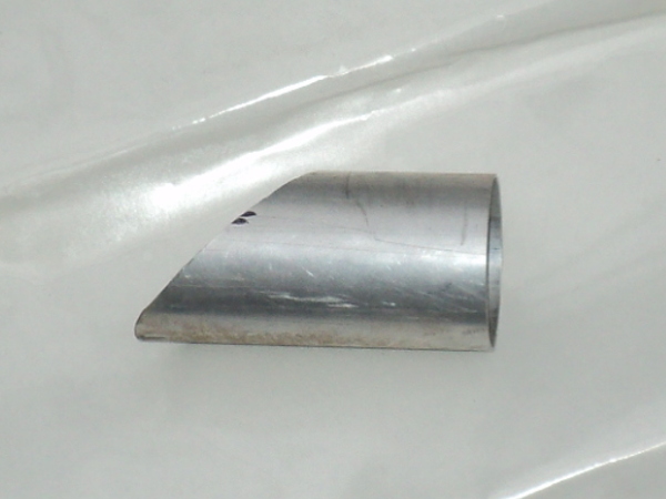
The sawcut alloy tube
These, when mounted onto the guard will fit onto the guard part way up it and give the necessary vertical surface, unfortunately though the plain cut end does not match the curves of the guard.
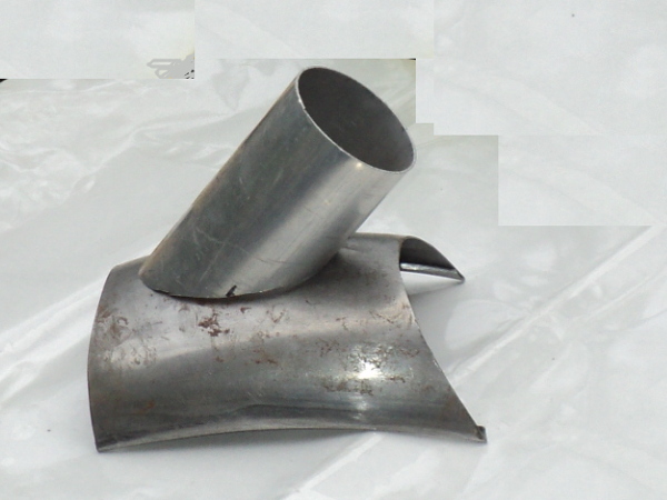
Showing mismatch between tube and mudguard, it only touches at the ends
However from fitting the guard onto the sidecar I had a short length of it spare
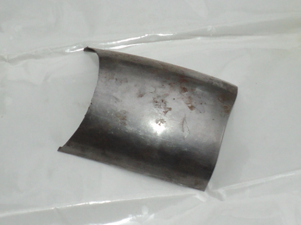
“Spare” length of mudguard
so I took this, fixed some 80 grit abrasive sheet to it.
I next took a black marker, used it to “black up” the cut end of the tube
“Blacked-up” end of tube
and then started rubbing the mount on the abrasive sheet.
Rubbing in end of tube to match mudguard
This gave me “witness marks” showing where the guard was contacting the mount and so, where the mount needed trimming back.
Rubbed end of tube showing “witness marks” where material still has to be removed
This was done using a Dremel tool and a sanding drum.
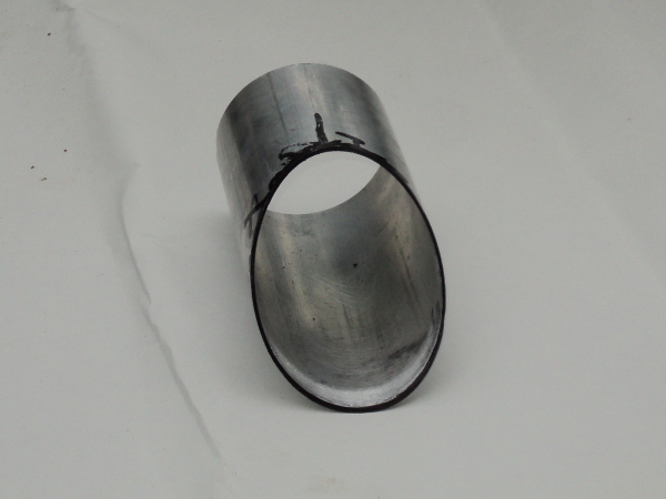
Repeated re-blacking, trials and trimming gave me a pair of mounts that were a reasonable fit onto the guard and which, given some rubber beading, would make a sound joint against it.
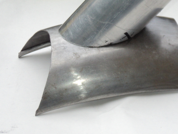
Tube matched to contour of mudguard
I now needed bases for the lights themselves. To make these I took a pair of 10mm thick alloy disks of about 85mm OD.
These were each chucked up in the lathe
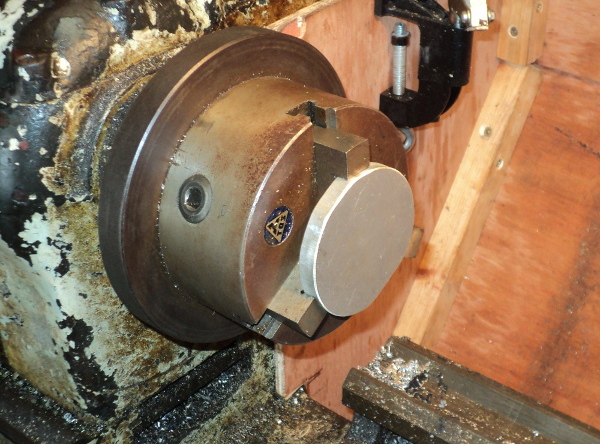
Raw disk in lathe chuck
and had a central 8mm hole drilled through.
After this they were removed from the chuck their place was taken by a short length of 32mm OD bar. This had its end faced flat and then had a central hole drilled into it. This was tapped to take an 8mm bolt.
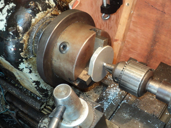
Disk centre drilled 8mm
This gave me a mandrel to work the disk on and so one of the disks was bolted to it, this meant that I could now turn the disk about it’s centre and it was able to have the edge turned down to size.
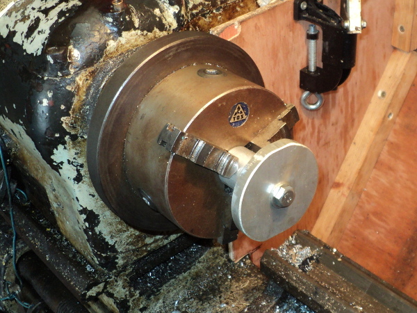
Disk mounted on mandrel for turning
This disk was now skimmed down to 75mm diameter, the same as the OD of the tube.
Next step was to turn a 4mm deep spigot on the disk to make a tight fit in the tube.
I then reversed the disk on the mandrel and another 4mm deep spigot turned on the other side, this time sized to mount the Hella lens onto.
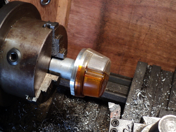
Disk turned to size and lens fitted
Suitable mounting holes were drilled and tapped into the alloy to take the lens mounting screws.
All that was now needed was to supply light to the lenses and rather than use incandescent bulbs I opted to use LED lights instead.
Going onto Ebay, I ordered up 4 amber, two red and two white LED marker lights. These mount with a 10mm stud on their backs.
As these are the equivalent of a 10 watt bulb the intention was to use two amber LEDs to supply each indicator,one white for the front running light and two reds for the stop light.
Going to the disks, I marked off the horizontal diameter through the lens mounting screws and drilled a pair of 10mm clearance holes above it. One one disk I then drilled a single 10mm clearance hole below the centre line and on the other a pair below the line.
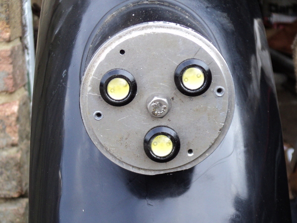
Front unit disk fitted with LEDs
Mounting two of the amber LED’s above the line gave me my indicators and the fitting the whites or reds below gave me my front running light and my stop light.
I needed a rear running light as well and so a similar but smaller unit was made up using a 50mm diameter LED rear marker light to supply the lens.
All that was left to do was give the mounts a lick of paint, mount them onto the guard via the central hole in the disks and to run in the wiring.
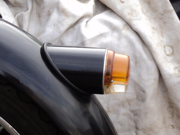
The completed light unit in place