When I installed the gearbox I had to guess the position of the spacers on the mounting studs. If I got it wrong it would mean that the gearbox would be too far over to the right and the chain sprockets would be out of alignment.
This is Not A Good Thing, it leads to heavy chain and sprocket wear and also the risk of the chain “derailing” and jumping the sprocket and locking thing up.
So it’s necessary for me to check the chain alignment.
First it’s just a quick visual by sighting from the rear of the bike along the rear-wheel and gearbox sprockets. This shows that the alignment is approximately right so I run a chain on to the sprockets and sight along that.
Not quite so favourable, looks to be off a bit to the right but not by the half-inch that misplacing the spacers would give.
So we’ll check the alignment of the primary drive.
Sight over the engine and clutch sprockets, looks OK so drop a chain across them and check it again, this time things line up nicely .
So, I have the primary chain line right, so the gearbox is where it should be, but the final drive is a bit out.
I’m using new sprockets on both the gearbox output and the rear wheel so which is out?
The problem amounts to that either the gearbox sprocket is too far to the right or the wheel sprocket is too far to the left
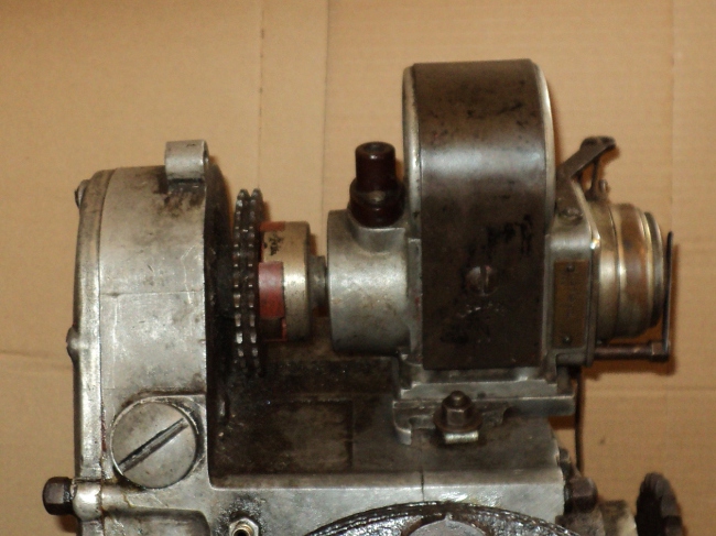
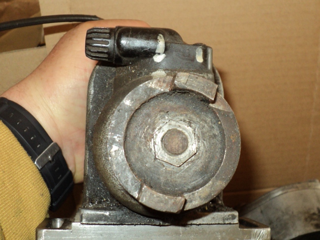
Since the primary chain-case has not yet been installed the gearbox sprocket is easiest to get at so let’s have a look there first!.
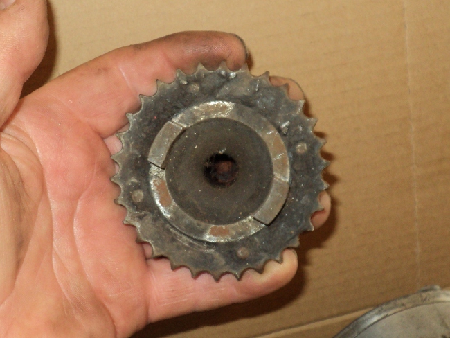
The sprocket is hard home on the shaft against the spacer ring so that’s not the problem, but it’s a new generic “Burman gearbox” sprocket so better compare it with the old one.
Obvious difference is that the Panther sprocket has a recessed face but the generic Burman has not, but all this will do is to allow the securing nut to sit deeper into it so it’s not that.
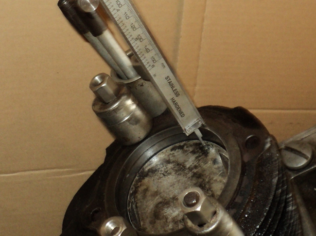
Then I spot it!
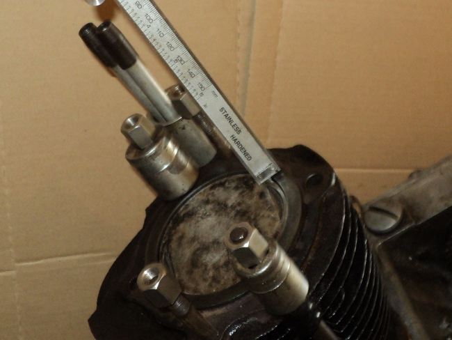
On the back of the sprocket there is a raised boss that bears against the spacer ring and they look different, check them out with a depth gauge and I find the Panther sprockets boss is 2.5mm deeper than that on the Burman.
This would move the Burman sprocket over to the right and closer to the gearbox and that’s exactly the problem.
Remedy is going to be to make up a new spacer ring to fit behind the sprocket to move it 2.5mm to the left and as this will reduce the threaded depth of the sprockets retaining nut I’ll need to dish the sprocket to match the Panther one as well, to make sure the nut has full engagement on its threads.
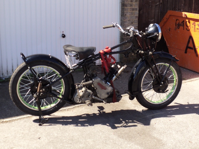
To finish I decided to fit the cylinder head so I could also fit the top engine mounts from it to the frame to remove the strain of the weighty motor being only half fixed in its frame.
I fitted one or two other parts as well and this is the result:-
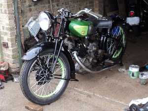
Nearside as is now
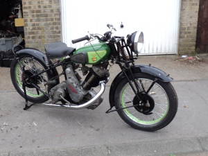
Offside as is now
It now seems obvious that I need to replace the push-rod tube, it’ll be cheaper than having it re-chromed and giving the alloy work a good scouring, I don’t want to bead-blast the alloy as that gives the wrong patina to the parts so it’s going to be scrubbing brush work with Jizer followed by soap and water.
I have boiled cases in an old wash-boiler before using soap-powder and they came up well but I no longer have a wash-boiler and they are not now readily available so that options now gone.