Monthly Archives: May 2013

The Mechanicals.(2)

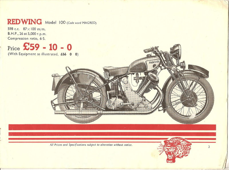
While I do not intend to split the crankcases of the engine they sadly need cleaning and to help with this I’m going to remove the timing case cover so I can clean it up separately and then paint the raised “Redwing” logo on it.

The cover is held on by three nuts which are on studs going through both crankcase halves and nine raised countersink head screws.

All of the screw heads have the slots damaged but with care and pressing the screwdriver blade hard into each slot as I unscrewed them I managed to get them all out.

To my surprise they are threaded 1/4inch BSW, I’d expected them to be either BSCy or BSF.

The old Whitworth thread is seldom found on vehicles as it is so coarse. The finer pitch BSF (British Standard Fine) thread is much more common, and on most older British made bikes the BSCy (British Standard Cycle, sometimes also called CEI or Cycle Engineers Institute) threads are often used.

However Whitworth is the strongest of the thread forms so I suppose its use in threads going into the aluminium alloy crankcase is not too surprising.

Fortunately all these thread-forms use the same range of spanners, and this brings up a frequent cause for confusion for newcomer owners of these elderly machines, they can see no relationship between the size marked on a spanner and the size of the nut that it fits,the fact that each spanner is marked as being for two different sizes adds to their problems.

The relationship becomes obvious when you realise that the sizes are specified on the stem diameter of the bolt in question, so a 3/4inch Whitworth bolt is 3/4 of an inch in diameter, but a 3/4inch Whitworth spanner is 1.300 inches “across the flats” as that is the size specified for a nut to fit a 3/4inch bolt.

A 3/4inch Whitworth spanner is of such a length that it is difficult to get enough pressure on the bolt to strip the thread. Since BSF is a finer thread than BSW it is easier to strip so a 3/4inch BSW spanner also fits a 7/8inch BSF nut and is the correct length for it.

In the Unified and Metric thread-forms the size stamped onto the spanner is the across the flats dimension of that spanner, so the system is specified on the size of the spanners used rather than on the bolt size. If you like one system is specified by the designer and the other is specified by the repair-man.

On removing the timing cover some thick, black, oily gunge dribbled out so I’m going to get some paraffin and clean out the insides of the timing case before I re-assemble things.

When I had a look at the timing cover I found that while the old gasket was intact, there were traces of an older gasket still on the crankcase joint face, this is the main reason why old Brit bikes have a reputation for being oil-leakers, it’s not so much the bikes at fault as the owners
making basic mistakes such as this so that the joint faces to not pull together properly, a tiny gap is left and the hot oil finds its way out.
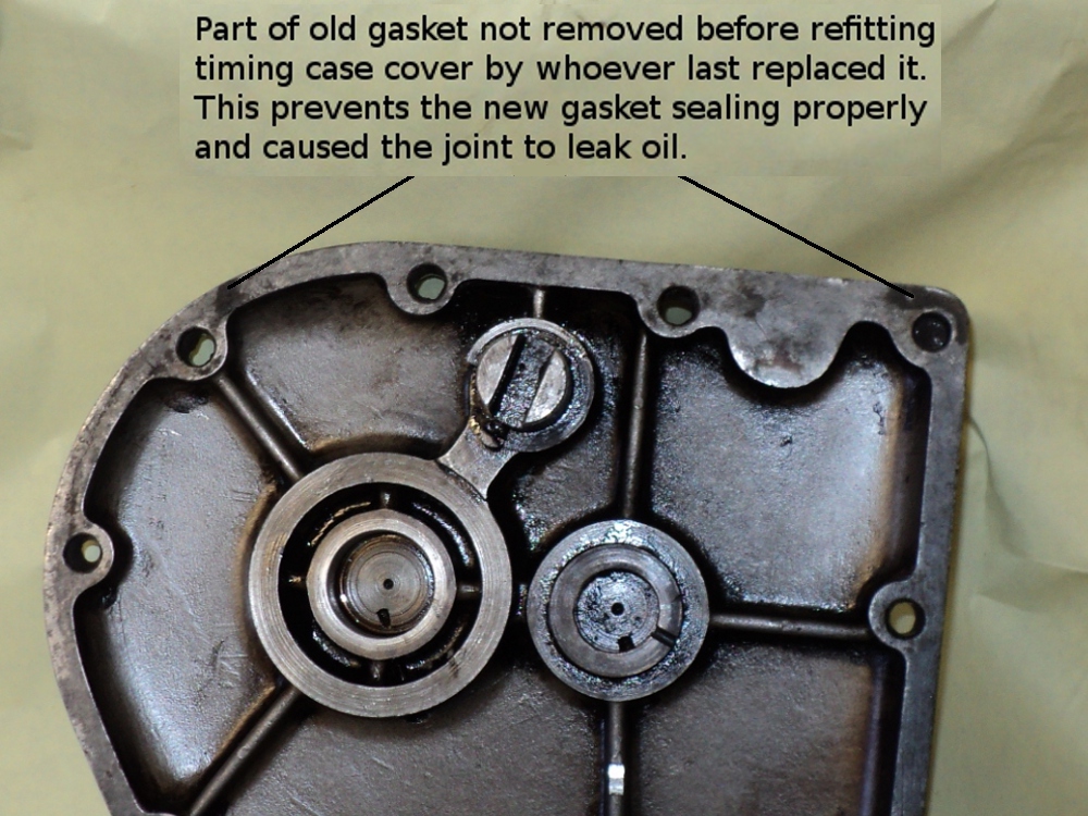
Inside Timing Cover

Inside Timing Cover

Anyway, I’ve put a set of case screws onto the list for the next lot of spares ordered.

Then it was just set to with hot soapy water and scouring pad to clean up the outside of the timing cover.

Timing Cover

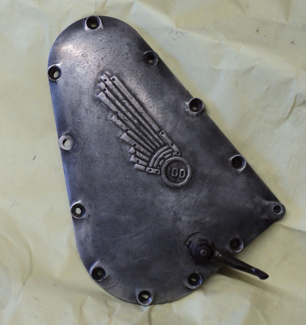
Outer appearance of timing cover

It appears to be cast from an alloy that has a relatively dark colour as while it has cleaned up quite well it does not have the bright silvery appearance of the casings on a more modern machine.

The Mechanicals.(1)

So far everything has been working on the running gear but that’s not all there is to do, the engine and transmission are still to start doing.

The engine has been on the bench for a while and it’s time to make a start on it.

The bottom end was sound when the bike was taken off the road so we’ll leave that alone.

There’s a choice of three barrels for her, one has a broken fin but the bore is only a little worn, however there are only two use-able rings on the piston, the middle ring being broken.

Another has sound finning but has been subject to a mild seizure, the bore is about half-worn and there are marks of the pick-up on both the piston and the bore. It’s only been a mild seizure however as the pick-up marks are light and the rings are free with no sign of smearing of the ring lands while the third barrel has sound finning but has the rings seized into piston lands.

All in all I’m going to use the first barrel but fit a full set of new piston rings after “breaking” the glaze on the cylinder bore, the idea of having one of the other barrels bored to suit that piston is a non-starter since that piston is standard size and both other barrels are over-size.

I’ve managed to find a set of new piston rings for it so next thing is to gap those rings and then to fit them.

An oddity that has turned up however is that the bike uses a slipper piston, something you’d only expect to find on a higher performance machine!

Slipper Piston

This is a slipper piston. (It is the piston with the seized rings)

Before fitting the barrel I’ll need to black it, what I’ve successfully done before this on side-valve barrels is to get the barrel clean and then spray it with “Smoothrite” black. The barrel is then oven-baked for an hour on low heat, there are certain advantages to the wife being away!

Then it’s given a second coat and the treatment repeated. This gives a durable, semi-gloss appearance and the only place it has not lasted has been on the exhaust port finning so it should be ideal for the OHV Panther barrel.

Front Wheel (2)

Once the rim had been prepared it and the new painted hub were taken back to John at North East Wheelbuilders to be built up into a complete wheel.

A little over a week later I received a call to tell me it was ready to pick up so it was back to John’s to collect it.

Job now was to apply the coachlines around the painted centre of the rim.

A couple of 4 inch lengths of 2 inch square timber were sorted out and a groove and a hole were made in both.

This allowed me to place the wheel between the open jaws of the Workmate with the axle resting on either jaw. The timbers were then placed with the groove over the axle and a bolt passed through both the hole and one of the holes in the Workmate’s top and the timber pulled down tight onto the top of the Workmate.

Now it was a simple job to place a paint-laden lining brush against the rim and gently turn it so as to leave the required coachline on both sides of the wheel.

Once the lines had dried out a coat of laquer was applied over them.

All that was needed now was to fit a tyre and tube.

According to the book, a 1937 Model 100 Panther wears a 3.25 x 19 inch tyre front and rear.

First thought was an Avon Speedmaster on the front and an SM MkII on the rear. Further thought said to fit an SM both front and rear as I intend to use this girl both as a solo and hauling the Steib S350 I currently have on the R12 and the Speedmaster is not a good tyre for the front of an outfit.

Problem arose on checking the websites when I found that the SM is no longer available as a  3.25 x 19.

I found that I could get a Mitas tyre, intended for front or rear fitment, on which a package deal was offered of tyre, rim-tape and inner-tube so it was a case of order it up and await delivery.

Last thing was to sort out the speedo drive.

Unlike more modern bikes this is taken from a gear-wheel threaded onto the bearing boss in the front brake hub.

This meshes with a gear on a right-angle drive that screws into a socket on the front brakes backplate.

First thing was to fit the new gear-wheel I’d got from the Owners Cub spares scheme.

This has an internal thread which matches the one on the outside of the bearing boss.

Now the old gear had been removed back when I started this rebuild in the 1980‘s and the  thread on the boss was gummed up with it having been taped over when I sprayed the hub so I wasn’t too surprised when I couldn’t get the thread to start, so it was down to clean out the thread with solvent and small “toothbrush” type wire brush.

It still wouldn’t pick up the thread, I must have spent a good quarter hour cleaning and re-cleaning the fine pitch threads on the boss and the gear when suddenly light broke through!.

The brake-plate and so the drive are on the right-hand side of the bike. This means that the drag from the drive would tend to unscrew the gear from the hub!

So I tried it the other way and the thread picked up straight away. It was a Left-hand thread!
I could have kicked myself for not realising it sooner.

Then it was just a case of measuring how far the gear-wheel was in from the brake-plate and screwing the right-angle drive box far enough into its socket to get the gears to mesh properly and the job was done and the wheel ready to fit.

Instruments (2)

With the front wheel away being built-up I decided it was time to sort out the speedometer drive.

This is taken from a big gear-wheel mounted on the brake-side front wheel bearing housing with a right-angle drive gearbox, similar to those used for a rev-counter drive.

First thing was the big gear, spec. for the Panther is a 44-tooth gear on the wheel mated to a 14-tooth gear on the drive box so I had a rake around in the “stores”.

First thing was the drive-box gear and I found that I had a pristine 14-tooth gear in stock, ideal!.

Then I found 4 of the big gears. While one was damaged beyond use the other three were more than usable, BUT! On doing a tooth count I found that while the damaged gear was a 44-toother, all three of the decent ones had only 43 teeth! Typical!!.

A swift check of the POC spares list showed the correct gear in stock though so that’s something else added to the list.

Then it was have a look at the right-angle drive.

There were three of these in the “stores”.

On inspection two were damaged and one seemed good.

The good one spun easily and there seemed no excess play on the output shaft so that was the problem solved, or was it!.

On a trial assembly it turned out that the drive-box output shaft was spinning anti-clockwise and, of course, the speedo head demands a clockwise input.

I then went to look at the other two ‘boxes and found that while the first box did have a clockwise output, the problem was that the output housing had the threads broken off so there was no way to connect a drive cable to it, not only that but it was very stiff to turn over and there was a lot of play at the output shaft, the output bushing was gone!

A look at the other and things got worse!.

The threaded input housing that it mounts by (it is screwed into a housing on the front brake plate) was totally stripped. Then just for a bonus on this box, it was seized solid and on closer inspection I determined that the input housing was bent.

So – “What to do?”. I got in touch with the company who had rebuilt the speedo-head and they put me in touch with a real “Name From the Past”, A Gagg and Sons! (I thought they’d closed down years ago!).

Yes they are still trading, but they have cut back to specialise in just Smiths speedos and rev-counters.

I had words with them over the ‘phone and it emerged that the “good” drive was probably from an ex-WD 16H Norton, given the paint finish on the box and the fact that the cover cap for the input shaft was painted red.

While they thought there was one “on the shelf” they offered to rebuild mine and reverse the drive for half the price of a new one, so I of course took up the offer! (Hey Panthers were made in Yorkshire remember, and you know what they say about Tykes, “Short arms and deep pockets!”. Not only that but I’m a Jock!, got a reputation to keep up you know.)

I sent all three boxes down to them in last Thursdays post and received a ‘phone call from them at lunch-time today, the following Tuesday, to say the job was done, and as they had
been able to use some parts from the other boxes it would be £20 cheaper than their quote, Even better! and you can’t ask for a better turn-round time on a repair than that.

Tank Attack, Final Phase

Once the paint on the tank had been given time to cure it was a case of masking the edges of the panel with a narrow tape that would follow the curve that I wanted.

After I had the panels outlined with the narrow tape I then masked off the rest of the panel so that when the dark green was sprayed onto the main body of the tank it would not get onto the light coloured area of the panel.

The rest of the tank was then rubbed down with 400 grit wet & dry paper so that there was a good keyed surface for the top coat and two coats of the dark green sprayed on.

The second coat was given 15 minutes to start to cure and then the masking was stripped off the tank.

Reason for this is that as the paint is still soft, stripping the masking tape off will not leave a chipped edge on the new paint, also the edges should still be able to flow a little and will then leave a softer edge between the main tank colour and the panel.

Painted Tank

Painted Tank

The tank was then left for a couple of days to cure and it was then gone over with polishing compound to rub down any minor irregularities and to give a gloss finish, then a layer of laquer was applied.

Now the tank had to have the coachlines added.

Traditionally this is done freehand using a special lining brush and it needs a steady hand and a deal of practice to be able to do this.

Fortunately there is away round it. You can get a special lining tape where there is a backing tape carrying two strips of masking tape the required distance apart.

You put this in place where you want the coachline, strip of the backing tape to leave the masking tapes and then carefully paint in between those tapes, strip the tapes off and there’s your coachline.

Tank p4epared for coachlining

Tank prepared for coachlining

Sounds easier than it in fact is as it is fiddly getting the backing tape positioned round a curve, it will take a bend but the tighter the bend the more awkward it is to get the tapes to lay flat and keep a constant line width but with a bit of time and patience you can get a good result. The extra pieces of tape at the rear corners are to give a “run off” so that I could take the paint to the end of the lines without worrying about over-running.

The tape is an American product, called “Finesse Lining Tape” and there is a choice of tapes to give various widths of line, it is also supplied to give double lines if you need them. Their UK agent is A.S.Handover and you can Click here for  a direct link to their catalogue pages of these tapes, not only that but they can supply you with  signwriters paint to make the lines with and even the pukka coachlining brushes if you wish to try the traditional way.

Once the tank had been lined I applied the transfers (or decals if you prefer the expression) and it was left it to dry for a while.

The whole thing was then given a couple of coats of laquer to seal everything and that was that.

Finished Tank

Finished Tank

I got the transfers from the Vintage Club’s transfer scheme who have transfers for over 350 makes. Click here to go to their site.

Knee Grips

In an earlier episode I told the tale of making the back-plates for the knee grips.

I wound up with these as flat plates and when bolted onto the tank a problem showed up, the plates were flat and the tank was curved!.

Flat plate

Flat plate on Tank

So the plates need to be contoured to match the curves of the tank to get the grips to sit snugly in place against sides of the tank.

This means the application of applied brutality, i.e. Hit it with a hammer!.

It is a bit more sophisticated than that really.

I obtained a sand-bag to give a firm but yielding surface to work against and proceded to gradually work the plates into shape using a both a rubber mallet and a hide/copper hammer.

It’s a case of gently persuading the metal to move where you want it, try it against the tank for fit and then hitting it again until the desired result was achieved. Because of the sand yielding under pressure you can readily mould the metal into a compound curve, just don’t try to rush things.

Plate after shaping and painting

Plate after shaping and painting

Then it just needs for them to be painted before they are fitted to the finished tank and the rubbers stretched into place over them.

On the Panel.

Now it’s time to look at finishing the fuel tank.

This is not in a single colour but is panelled.

Originally my old lady would have had her tank mainly in chromium plate with cream side panels with a broad red line outlining the panels, as seen in this clip from the 1937 sales catalogue.
1937 Catalogue_03

1937 Sales Catalogue
When I first got her the tank was in a two-tone finish, chrome and rust!

To get her on the road I just wire-brushed the rust off, applied a coating of “Phoscote” and that was that!.

The chrome was heavily pitted and while in theory it would be possible to have the tank re-chromed the amount of polishing required to get down to a suitable finish before re-chroming it was not practical, not only that but it would seriously thin the tank body so I needed an alternative.

This turned up at the National Motorcycle Museum in the 1933 Model 100 seen at the head of this blog and I decided to use this finish of a dark green tank with light green panels.

After playing round with colour samples I settled on a light lime green for the panels and the old British Racing Green for the main body so it was pop down to the local car body shop suppliers to see what was available.

The tank had previously been primed and rubbed down before the hiatus in this restoration but had become a little chipped and marked over the fallow years so I gave it a few coats of primer followed by a witness coat and rubbed it down again.

This didn’t take long as the finish I started with was quite good to start with.

Now the main body of the tank is to be the dark green, so I first painted the tank in the light green!.

Why? Because it is much easier to mask off a convex curve that it is a concave one, there is much less risk of having the second colour creeping under the masking tape as it is not rucked at the junction between them and if you only paint the area of the panels you wind up with a junction line showing in the darker green area.

Painted Tank

Painted Tank

The tank was then left for a week to harden off before I even thought of masking it so that the paint would not lift with the masking as it was removed.