Monthly Archives: August 2013

Bearings Down

I’ve known from the start that the kickstart return spring was broken, but otherwise the gearbox seemed OK, it was selecting gears and turning over in all four gears smoothly, with no roughness of feel to indicate a bad bearing.

I got a new return spring at the weekend and so went to fit it. As this is a grease-lubricated gearbox I could not just take out the drain plug and empty it before I started so I expected a bit of a mess but last night I broke the seal around the outer cover of the case and left it to drip overnight.
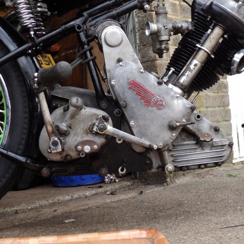
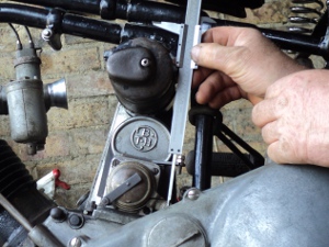
BGearbox

The Gearbox

This was more succesful than I expected as when I took the outer case off completely this morning there wasn’t that much grease left in the ‘box and a fair bit of gloop in the catch pan, I suspect it may have been filled with a 50/50 mix of grease and oil, a not uncommon trick back in the day.

Open Gearbox


With Outer Cover Removed

It quickly became obvious that the kickstart spring had broken, about 2 turns from its inner end, so I removed the kickstart lever from its shaft and then the quadrant from the case.

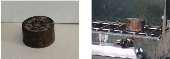
I had an old 5 litre oil can with the side cut out and with about a litre of paraffin (kerosene) in it, along with a paint brush and a couple of toothbrushes (Sainsbury’s cheapo’s at 18p a pair) and used them all to wash out the outer case.

Dismantled controls

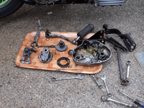
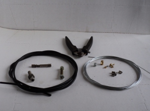
Dismantled contents of kickstart case

Once I’d replaced the spring I decided to check its meshing gear and the kickstart ratchet for wear so I undid the nut on the end of the mainshaft and removed them. While doing this I noticed that the mainshaft bearing “looked wrong” and on closer examination found it was frozen, with the mainshaft turning in it, the mainshaft is intentionally a slip fit in the bearing.

Swift replan of things!, the gearbox had to be stripped.

In theory the bearing can be replaced on its own without this but it’s not a good idea to replace only one of a bearing pair, and it’s a total gearbox strip to do the drive end bearing.

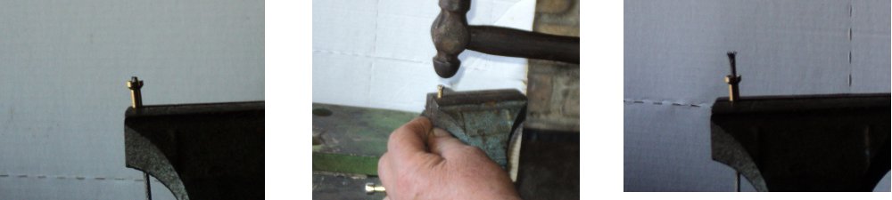
According to the book you remove three nuts and the inner case will simply slide off along the studs,

So says the book but needless to say this did not happen and the inner case had to be wangled along a bit and then the gears pushed back into the main casing before the inner case could be finally wangled off.

In these Burman ‘boxes the selector camshaft runs in a crowded roller bearing in the inner case and when that case is removed the rollers promptly drop onto the floor and are lost, but I knew about this little”feature” and so had put a large cardboard tray under the gearbox to catch them as they fell.

Once the sticky mass of grease in the tray was checked through there they were, 11 little rollers, but there should be 12 of them!. So check the gearbox shells and shafts, No, check the floor, No, no sign anywhere.

So next was to take out the gears as a set, first remove the mainshaft itself through the primary chaincase, remove the indexing pawl from against the camshaft and the whole cluster just lifts out.

Check the gears, even between their teeth, still no sign of the missing roller but the gears are bright clean without any sign of corrosion and, while used are still eminently serviceable. The mainshaft shows no scuffing or other wear where it runs in the bearing at the kickstart end so it cannot have been running in the bearing, which must have frozen with standing for so long and not when last in use.

All that’s left to do is to take the shell out of the bike to replace the drive side bearing, while it is possible to do it “in situ” I want to clean the case out completely.

Easy way here is remove the rear mudguard and drop the shell out to the rear, and as I have a couple of jobs to do on the rear guard anyway it will kill two birds with one stone as it were.

On checking the lists both bearings, as well as new camshaft rollers, are available through the Panther Club so I’ll order them up.

Under the Wire

You control the various systems of a motorcycle through Bowden cables,‭ ‬a crafty way to transmit a push-pull action through a flexible cable.‭

Where you have a modern machine you can just walk into the dealers and buy a replacement cable over the counter but Panther ceased manufacture back in the‭ ‬1960‭’‬s so this option is not available to me.

Since I require a full set of cables for the bike I am going to have to make up my own from scratch.‭

You can buy so-called‭ “‬universal‭” ‬cables.‭ ‬These have one end already made up for you,‭ ‬what you need to do is cut the cable to length and then either use a solderless nipple or solder one of the the loose nipples supplied in the kit onto the free end of the inner wire.

These‭ ‬cables cost around‭ ‬£11:00‭ ‬each however and there are a total of eight cables on the bike.

All of the various components are available however, from a number of sources and at a‭ ‬noticeable cost saving . ‬I’m getting them from Vehicle Wiring Components‭ since I’m also using them for the wiring and associated electrical parts I need.

DSC1047
Cable components and cable cutters

A complete cable consists of an outer casing,‭ ‬an inner wire,‭ ‬a pair of ferrules,‭ ‬an adjuster and a pair of cable nipples.
The casing comes in a range of sizes‭ ‬varying from the very light‭ “‬No.‭ ‬0‭” ‬used for bicycle gear controls to the very heavy‭ “‬No.‭ ‬5‭” ‬used for car hand-brakes and trailer brakes,‭ ‬on a motorcycle normal use is‭ “‬No.‭ ‬1‭” ‬for the throttle and‭ ‬other light-duty controls and‭ “‬No.‭ ‬3‭” ‬for the front brake and clutch.

There are,‭ ‬of course,‭ ‬a similar series of inner wires associated with these casings,‭ ‬along with the appropriate sized ferrules and a range of adjusters and nipples to suit the various controlled mechanisms.

What I’m making up here is a magneto‭ (‬or ignition‭) ‬advance/retard cable which uses a No.1‭ ‬casing.

First thing to do is to see what nipples are required for the cable,‭ ‬in this case I need two‭ “‬drum‭” ‬type nipples,‭ ‬each‭ ‬1/4‭ ‬inch in diameter by‭ ‬1/4inch thick.

Next is to measure the length of casing required so I’ll screw the adjuster‭ ‬into its mount and run the casing up to the handlebar lever,‭ ‬making sure there are no tight bends and there is enough slack for the handlebars to turn.‭

Once I have the correct length the casing is cut to suit.

Because the casing is basicly a spring with the coils touching each other the while it can bend its overall length will stay the same.

Once it has been cut to length you often find that the cut end of the casing will partly block the centre bore intended for the inner wire,‭ ‬so the two ends of the casing will need to be dressed off square and then a ferrule fitted to each end,‭ ‬I secure them with a dab of‭ “‬Super Glue‭”‬.

The inner wire needs to be same length as the casing PLUS the extra needed to reach the nipple sockets on the lever and the magneto so theseadditional lengths need to be measured.‭ ‬When cable lengths are quoted the convention is to work to the‭ “‬pull‭” ‬side of the nipple so if you have a‭ “‬book figure‭” ‬for the cable lengths you need to‭ ‬remember to allow for the short lengths inside the nipples,‭ ‬in a‭ “‬worst case‭” ‬you could have an inner cable a half-inch too short if you don’t‭!‬.

measure
Measuring distance between adjuster and lever

Once the length needed is known then you need to cut the inner wire to length without splaying the end,‭ ‬problem here is that it’s a hard high tensile wire‭!‬.

While it can be done with a sharp cold chisel I use a pair of cutters,‭ ‬designed for the job,‭ ‬that I got from a local bicycle shop and they make this part of the job easy.‭ ‬You can see the cutters behind the casing and wire in the first picture.

Moving on to the nipples,‭ ‬you’ll find that there is a hole across their diameter and that one end of the hole is counter-sunk.‭ ‬While the nipple does have to be soldered onto the inner wire it is‭ ‬not the solder that secures it in place.

‭ ‬The nipple has to be slid onto the end of the wire with the countersunk end pointing towards the end of the wire.‭ ‬Then the end of the wire must be splayed into the countersink cavity.

strip1Cable end ready to splay                Splaying end with small                  Final  result.                                                                  hammer

This means that the cable will not pull back through the nipple because the splayed end of the wire  sticks in the countersink.‭ ‬Then once the cable end is soldered,‭ ‬the solder and the splayed end of the wire together form a conical wedge that cannot pull back through the nipple.‭ ‬It is however a good idea to put any captive adjusters in place before fitting the nipples‭!‬.

Next job is to solder the nipples in place.‭

The secret of soldering is to have enough heat available,‭ ‬the whole job‭ ‬has to be hot enough to melt the solder so a small electrical type soldering iron is not man enough for this job‭!

What I use is a solder pot.‭ ‬I have a block of brass with a one inch diameter hole one inch deep bored into it and filled with solder.

pot
Solder pot                                                                 Heating the solder pot

This is heated‭ ‬until the solder is molten,‭ ‬Because the brass block acts as a heat reservoir there is no worry about bad joints through the job not being heated through and through‭ ‬and there is no need to keep the flame on it all the time.

The nipple is slid back from the end of the inner wire,‭ ‬the wire end dipped into a tin of paste type non-acid flux and then into the pool of molten solder.‭ ‬This‭ “‬tins‭” ‬the wire with solder,‭ ‬the excess of which can be tapped off on the top of the brass block.

The nipple is now slid up against the end of the inner wire and pulled hard up into place,‭ ‬the nipple and wire end dipped into the flux and then put into the solder pool for several seconds.

making
Nipple dipped into solder                                                        and allowed to cool

The flux will melt and hiss a bit and then you will see the solder has‭ “‬tinned” the end of the wire.

It is then taken out of the pool and quickly,‭ ‬before it has a chance to cool off,‭ ‬the nipple is again pulled into place at the end of the wire,‭ ‬if the nipple pulls off the end of the wire when you do this then you know that you did not make a good enough job of splaying the end‭!‬.‭ ‬The idea here is to make sure the splayed end is hard home in the countersink.

Now pop it the flux again and then back into the solder pool for another few seconds,‭ ‬give it the chance to heat through.‭

Take it out of the pool and hold it in a vertical position,‭ ‬countersunk end down,‭ ‬till the solder has hardened.

job done
The final result

All you need to do now is to assemble the complete cable, solder the other nipple onto the other end of the inner wire and that’s the job done.‭ ‬You will need to check the nipples can move easily in their sockets,‭ you ‬may have to dress-off‭ ‬a little excess solder from the nipple for this, then‭ ‬lubricate the cable and fit it into place.

Done properly a cable made up like this is very secure,‭ ‬I once had a cable I made like this tested on a tensometer and the inner wire broke before the cable end slipped through the nipple.

That’s the magneto cable made up,‭ ‬that leaves me‭ ‬with the valve-lifter cable,‭ ‬the air control and the throttle cables to make up in No.1‭ ‬cable,‭ ‬then‭ ‬there’s‭ ‬the clutch and the two front brake cables in No.3‭ ‬cable and the rear brake in No.‭ ‬5‭ ‬cable so there’s a fair bit of work to do there‭!‬.‭