Back in the early days of biking (and of cars!) what you bought was the basic machine.
“Luxury” items such as lights were added after-market by the owner to suit their personal preferences and this meant that they came without any electrics other than a magneto for the ignition.
For lights there was the choice between acetylene gas powered lights and electric ones, gas lights having the advantage of being a complete and separate system whose generator only needed to be kept filled with carbide and water but needed regular cleaning and refilling while an electric systems generator needed to be driven, a gas system was also cheaper than an electric.
A cycle type dynamo driven by one of the wheels was tried but found wanting so it went to being driven from the engine, but it also needed a “power storage unit” that is:- a battery.
Since it was an “add-on” this meant that the generator somehow had to be bolted on somewhere near the engine and then had to be driven from it somehow, even today on a car the alternator still is a “tagged on” part like this even after over 100 years of development!, but modern bikes have moved on from this primitive system.
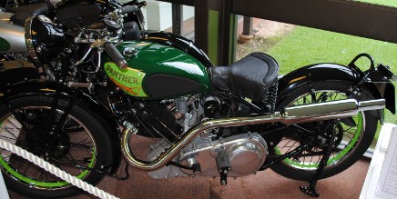
However my Panther is a 1937 machine.
At this time, while bikes no longer came without lights as a standard fitting this was a recent innovation, as a “for instance” my 1929 Triumph was supplied without lights, they were still basicly a “bolt on” accessory.
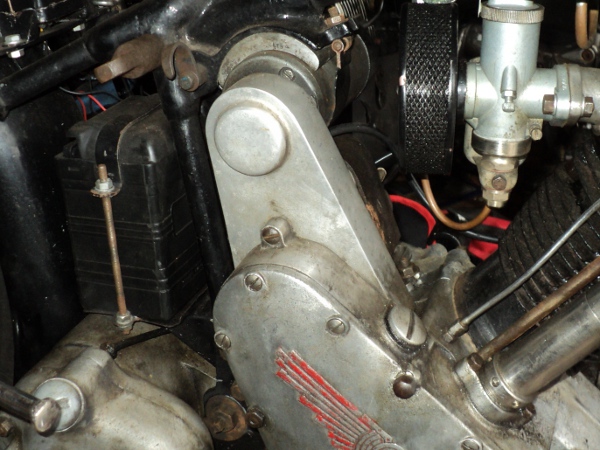
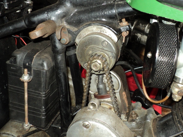
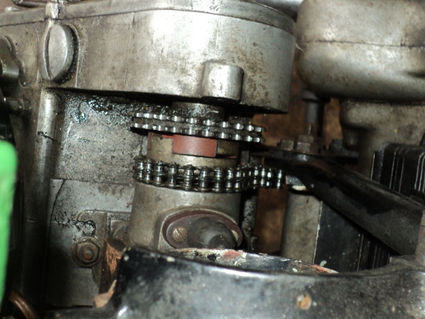
The Panther has a 6 volt 36 watt dynamo bolted to the frame top tube, just in front of the seat tubes, and this is driven from the magneto’s drive coupling by a small duplex chain, this chain having a cast aluminium cover.
This drive is a known weak point on the bike, being prone to wear and possible breakage, and in the event of breakage it can cause damage to the engine housings and stripping of the timing gears in the event that the broken chain jams the magneto drive.
While it was not available back in 1937, there is a safer modern alternative available in the form of a toothed belt drive and I’ve decided to go this route since the dynamo chain on the old girl is showing signs of wear, as are the drive sprockets.
Investigations on the internet soon showed details of what was available in the form of toothed belt pulleys and drive belts as well as sources of supply of these.
On the Panther the drive sprocket has 30 teeth on it while that on the dynamo has 11, giving a 2.7 to 1 “gear up” in the drive, a maximum RPM for the dynamo in the order of around 7,000 RPM and of some 2,500 RPM at 30mph.
I have fitted an electronic 12 volt converter onto my bike and since a downside of this is that it has a higher dynamo “cut in” speed than at the original 6 volts I’m going to take advantage of the conversion to uprate the dynamo speed a little and have decided on the use of a 14 tooth pulley on the dynamo and a 44 tooth as a driver.
This will give a dynamo speed of nearly 3000 RPM at 30mph and a maximum of around 8,000 RPM. From the use of these dynamos on other marques of bike I know this is well within the capabilities of the dynamo.
So I ordered up a pair of pulleys and a suitable toothed belt, which arrived two days later.
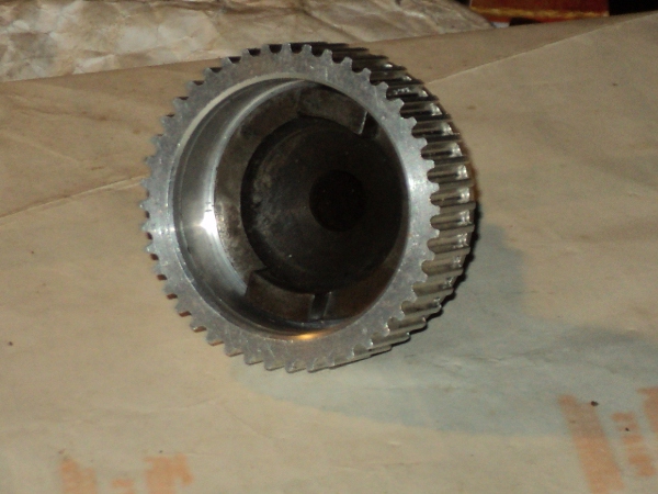
The small pulley turned out to be the neat belt width, there being a pair of cheek flanges to retain the belt in place and it was made from steel while the larger pulley was a wider, aluminium, unit and without the flanges so this will allow for a small measure of misalignment between the pulleys. Both pulleys were supplied with a “pilot bore” in their centres.
First thing was to sort out the drive pulley so as I have a spare drive coupling I decided to use that for the conversion.
This had two chain sprockets, one riveted either side of a flange to give a duplex sprocket. These rivets heads were accordingly ground off using a Dremel tool, the rivets driven out and the sprockets removed.
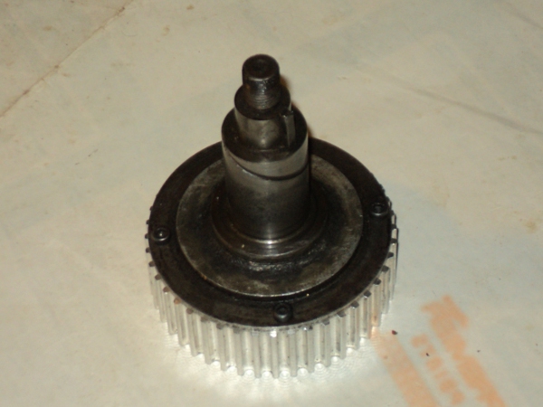
Once the coupling was offered up to the larger of the pulleys it was found that this flange was slightly smaller in diameter than the pulley and the rivet holes matched nicely with the side of the pulley and so could be used to mount the two together.
The pulley centre was then bored out on the lathe to match the register on the flange that had formerly located the outer sprocket. It was then counter-bored to give a good running clearance for the magneto coupling.
This coupling is a variation on an Oldhams coupling which has the advantage that it can cope with the two sides being a little out of alignment in both plane and angle but it does needs some room to “work” to do this.
Once the pulley had been bored out it was fitted onto the location flange and the position of the rivet holes marked out on it.
The original rivets were 1/8 inch diameter so it was decided to use 3mm Allen cap head screws in their place so the pulley was now drilled and tapped to suit and then secured in place, the screws being secured in place with Loctite.
That left the dynamo pulley.
The dynamo has a tapered shaft for this to mount onto. This taper is a standard size across all makes of dynamo, it also is the same as that used on magnetos and is a taper of 1:10 on the diameter.
To machine this the top slide on the lathe needs to be set to the correct angle.
To do this I set up a test bar, known to be true, in the lathe and the top slide was adjusted to run true to this.
A 5 inch long ground tool-bit was then put in the tool-holder on the top slide and this was adjusted parallel to the test bar.
The top slide was then reset so one end of the tool-bit was against the bar while a ¼ inch drill was just nipped between its other end and the test bar.
This meant that the top slide was now set to cut a 1:20 taper on the radius, 1:10 on the diameter.
I then chucked up a length of half inch bar, cut a trial taper on it and tried an old chain sprocket on it.
Needless to say it was not quite right but given another couple of tries, making small adjustments to the slide setting each time, and I had a satisfactory result.
All that was left to do was machine the new pulley to suit and all was ready to fit to the bike.
To Be Continued
