A Bit More Support.

A downside of using the Panther as a solo is that, being a rigid-framed machine she does not have a centre stand, any time you stop it’s a case of working your way to the back and heaving her up onto the rear stand. While this stand does have a “Roll-On” foot it’s still a hassle.

Unfortunately Panther never supplied a side stand for their machines and because they do not have an underframe it is not possible to fit one of the after-market “clamp-on” universal fit side stands.

However, between the wars there was a stand available that could be used and there is now someone manufacturing these once again.

The stand in question is the “EsWay” and a modern version is available as the “Vintelle”from Mick Hall Engineering in Otley.

CREATOR: gd-jpeg v1.0 (using IJG JPEG v80), quality = 90

1928 Advert for Esway stand

I made contact with him to enquire as to its suitability for an M100 Panther and discovered that his first one had actually been fitted to an M100 so I ordered one up, this was late on on Tuesday so the order would be processed on Wednesday. It was delivered on Thursday morning!

Packed stand kit

The stand came better packed than just about anything else I have bought on-line, putting the standard Ebay and Bangood efforts to shame, along with a comprehensive fitting guide, so it was out to the garage and get on with it.

The stand fits across the rear sub frame, as far forwards as is practical, about level with where a centre stand would fit. It comes with various fittings to suit a wide variety of machines so first thing is to sort out the best ones for your purpose, then a re-read of the fitting instructions before lifting the spanners!.

As the Panther has an exhaust on either side I selected the lower mount with the greatest stand off and assembled it loose onto the lower chain stay and attached the stand to it.

Lower bracket mounted on bottom chain stay

There’s a choice of two upper mounts in the kit so next thing was to see which was needed.

I extended the stand to make sure it would clear the nearside exhaust and made my selection to suit, fitting it round the upper chain stay.

All that was left to do was to snug everything up and make sure the stand foot had clearance and that it was clear of the ground when the bike was laid over into a corner, not a good idea to have it fouling!.

Upper bracket goes onto upper chain stay and stand mounts across the brackets.

The only criticism I have is that the mountings supplied for it are slotted pan-head set screws, I would have preferred to see Allen cap screws or even just simple hex head bolts, a minor niggle when all is said and done.

A Bit Off The Side.

With the way things are at present I’ve taken the sidecar off the R12 to ride it as a solo for a while.

This is not a difficult job, worst part is manoeuvring the detached sidecar around.

All it takes is to slack off the two bell clamps, remove the bolt through the upper clevis of the upper brace, unplug the lights and I can wheel the sidecar away, not even a ten-minute job!.

When it comes to replacing it things are just as easy, and because of the design of the sidecars fittings I will not have to re-align things, it literally just plugs straight back on.

However, taking the sidecar off brings with it another problem, but it’s one I would have had anyway, Tyres!

Both tyres on the old lady are a bit worn and are well past their “use by” dates, so it’s been onto the Internet to see what is available.

With the old girl having been built back in 1940 she runs on the old imperial sized tyres. While these are still available choice is a bit limited.

Strangely enough, if I wanted sidecar use tyres it would be easy because suitable tyres are still in production because they are used on pre-war cars such as the Austin Seven. Being a sidecar tyre though they have a flat profile and that does not give good handling on a solo machine.

A rake around the Web turned up some options using modern tread patterns, not ideal for use on a vintage bike, and then I found a MITAS tyre in the correct size and with an older profile, one more suited to the age of the bike.

These are of East European manufacture and while possibly not really suitable for use on a modern “crotch rocket” they are perfectly adequate for use on an elderly side-valve machine like the R12, so it was out with the card and order up a pair, along with new tubes and rim-tapes.

Even with current hold-ups delivery only took a couple of days and now it’s just a case of fitting them and now is an ideal time as the current heat wave heats up the new tyres and make them more supple and easier to fit.

When it came to removing the old tyres they showed their age, you could just about strike a match on their side walls they were so stiff and hardened!, I was glad of the extra tyre lever I had bought some years ago that’s almost half as long again as the standard ones that came in the R80 BMW’s tool kit!.

I fitted new inner tubes and rim tapes while I was at it, after all the old ones had been in there for some 30 years now, I checked the date code on the old tyres, 1984! they were well time expired even if they did still have reasonable amounts of tread left.

The new tyres went on easily as they were warm, I cleaned up the rim bead areas, soaped the tyres beads inside and out and did not need the levers to mount them, the one bead slipping on with hand pressure and the other being “walked” on. As soon as the new tyres were fitted I put about 40 psi of air into them and bounced them all round their perimeter and the beads snapped home without any problems.

Then it was just a case of adjust the tyre pressures and refit the wheels.

What’s New?

It’s been a while since I posted anything on this blog, too long! But there’s not been much happening with the bikes as they’ve been running well. However I’m feeling in need of a change now so –.

I’ve taken the sidecar off the big Panther, not the easiest of jobs when working on your own, but do-able, the body is now up on a pair of trestles in the shed and the chassis is in the back yard.

The Panther now stands as a solo in the garage, but she’s not on her own as the old BMW has been brought out of storage and is standing beside her, they make a good pairing, the 600cc 1937 Panther M100 and the 750cc 1940 BMW R12.

Although the Panther has the smaller displacement engine of the two she is the more powerful at 26bhp to the BMW’s 20bhp, but the BMW is a twin cylinder side-valve with a heavy external flywheel so is possibly the better slogger of the two, still neither was intended as a sports bike.

Anyway the BMW is set up with a full set of Steib quick release sidecar fittings so once I have the chair set up for her I can drop it on and off in around five minutes work, useful!!

Now, what does the BMW need doing to get her in commission again?

Well her battery is an AGM sealed unit and has survived her spell in the storage unit. It was still showing about half-charged when I put it on the charger. She is magneto ignition and that’s sparking well but I’ll treat her to a new pair of plugs.

How about oils?, well oil is cheaper than metal so it’s new oil all round, and owing to her age it’s an old-fashioned non-detergent type oil. Equally I needed new drain and filler plug gaskets.

On a machine of this age these should be the hollow rolled-copper type rather than the solid aluminium ones BMW now supply. A quick rake round on ebay soon found a supplier of these in the necessary 14mm and 18mm sizes.

Rather than run her up to hot on the old oil I let her drain out overnight and then it was just a case of fill the engine to between marks on the dip-stick, fill the gearbox and final drive until the oil reached the bottom of the filler hole threads and that was that.

Now the acid test! I put a half-gallon of fuel into the tank, no leaks visible! GOOD!!, turn on the tap (which way is “ON” and which is “RESERVE”??, I can’t remember!! ).

OK, the carbs filled up so a good tickle on each carb, crack open the throttle and turn over the engine several times to prime the cylinders, then it was just switch on the ignition and kick her over.

While she fired she didn’t pick up so a tad more throttle and try again and the old girl was running again! Tick-over balance is a bit off but I’ll need her warmed through to set that up so it will have to wait.

Now I know she’s a runner what else needs doing.

An immediate obvious is indicators!. Last time out she was hauling the chair.

I know it’s non-original, but on modern roads an outfit NEEDS indicators and now you can use LED units without overloading the electrical system so she was fitted up with lights on one side, the others being on the chair. So it’s get another pair of indicators and fit them.

I had to make up (and paint) a set of mounting brackets for them, run in the wiring and then tap it into the circuit to the sidecar indicators, a quick check and they were working..

Next thing was cosmetics, the front mudguard needed some serious touch-up where the paint has been badly scarred and had started lifting while the old lady had been in the storage unit.

Fortunately it can be redone while still on then bike as it would be serious hassle to remove it and then a dose of “T-Cut” after about a fortnight’s curing and then a polish job should see things OK.

As I’m writing this she’s standing in the garage with the first top coat on the guard giving it time to harden off before she’s put away for the night, another coat tomorrow should then see it ok.

I can’t really complain as both guards were in a bad state when I got the bike back at the beginning of the Eighties and they needed serious patching to be made usable, and she has seen some serious mileage since then!

= = = = = = = = = = = = = = = = =

When I had a look at things the next day I was very happy as to the finish, the “Craftsman” paint I was trying out as a replacement for my old favourite “Tekaloid” came through with flying colours.

Only trouble was the contrast with the old paint, this had weathered over time so the new paint stood out like the proverbial on a barn door!.

So I broke out the “T-Cut” and gave the guard a good rub down and that did the trick, you no longer noticed the repair unless you looked closely, snag is I now have to do the rest of the bike to get it to match the front mudguard!.

The R12 is quite heavily pinstriped so this repair has left a gap in the lining on the front guard that I’ll need to patch, so I now need to break out the lining brushes.

Lining is properly done free-hand and the difficult bit is getting a tight curve without smearing. My way round this is to mask out the line so that any smear goes onto the masking tape, problem is that with the BMW double line I’ll need to do one line and let it harden off before I can mask off to do the other.

I’ve also had the old girl out on the road for a run to see how things were.

I found that while she was willing to start and run, the start-up from cold was not as willing as it used to be and she was very reluctant to start from hot.

What I’ve done today is to treat her to a pair of new plugs, the old ones had been in for a long time now. I’ve also had the carburetters off and stripped and cleaned them, they have been standing for a couple of years and what fuel had been left in them had dried out and left a “varnish” of crud inside the passages and jets.

Fortunately she’s running on a pair Amal 276’s and these are an easy carb to strip down and clean.

I’ll need to synchronise the slide opening before I take her out again and while that’s a fiddly job it’s not that difficult.

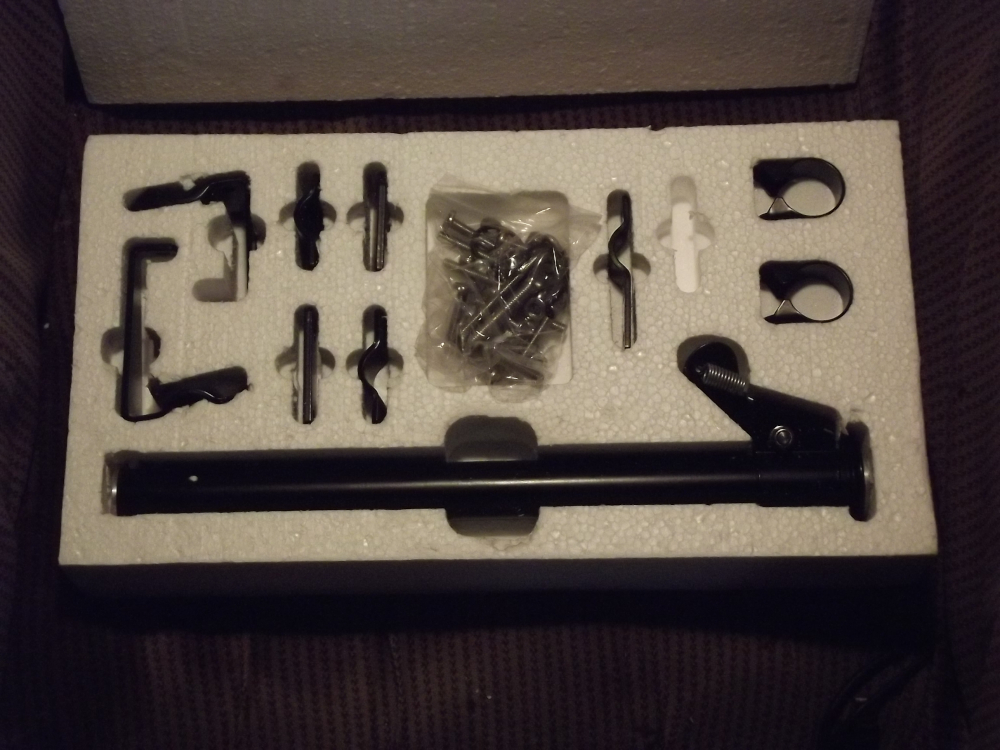
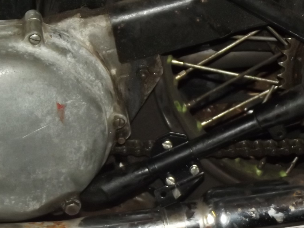
I’ve also offered up the sidecar chassis to the bike, before I actually fit it I’m wanting to rig a sidecar brake. I had a sidecar brake on the Panther outfit and found it useful, after all the bikes brakes are from the 1930’s and brake technology has come a fair way since then so every little helps.

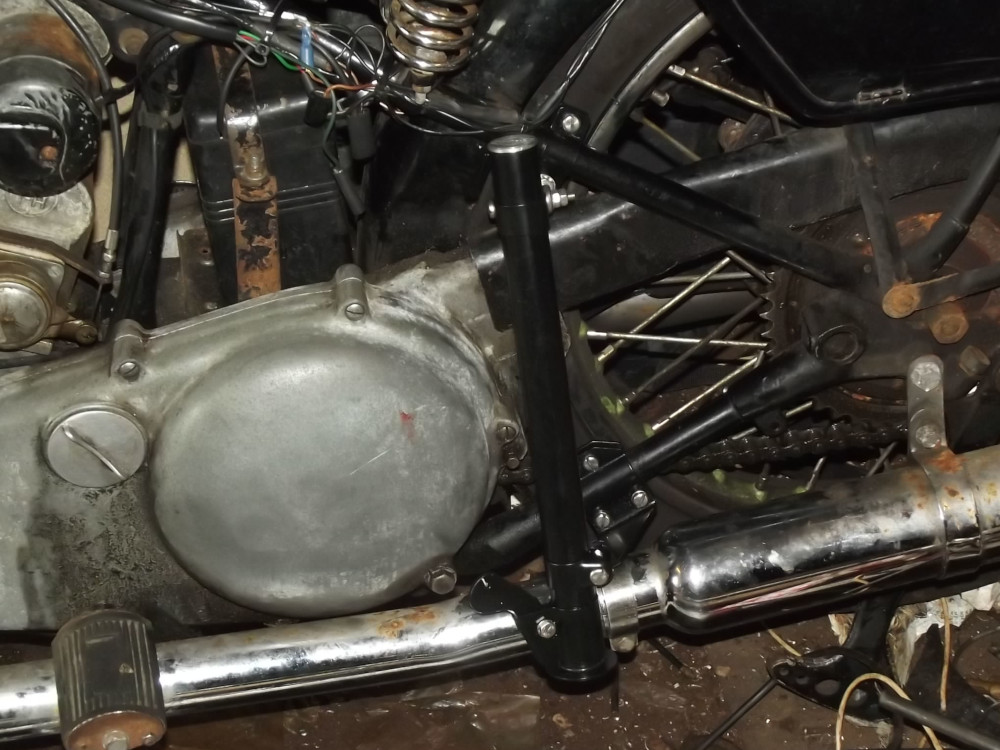
The rear brake on the R12 is with a heel operated pedal on the right-hand side. What I’m doing is to mount a pedal onto the sidecar chassis with a lever coming straight across to the bike and level with the rear brake pedal so its pad lies alongside the bike’s one. This means that when I apply the bike’s brake I’ll also apply the sidecar brake as well, and by rocking my foot I can vary their relative pressures.

However I’ll also be able to apply either brake on its own to give differential braking which can be useful to assist in cornering.

Only thing is that while I’ve the brake pedal set up I’ve still to arrange the cable fitment at the drum end of the system, as a “By The Way” the chassis I’m using is from an LS200 Steib. The wheel us from a Ural/Dneiper, a half width hub that looks in keeping with the R12 and the brake mechanism is an Enfield type from a rigid-framed Panther.

A Strip of the Old Bike 6

While this project set away as a touch-up job of the bike there’s also a bit of work needed on the sidecar, mainly cosmetic but there’s a bit on the underside will need a portion of a panel replaced.

There’s a place under the seat where water can accumulate, remember it is an open sidecar! and the base panel has corroded through here. It’s not at a point that’s structurally important so what I intend is to simply seal up and re-inforce the existing panel.

Rather than weld the new part in place, which could result in places where more water could accumulate I’m going to use epoxy to fit it and I’ll sandwich some glass mat between the old part and the new.

Another touch-up is at the nose of the body where there is an area where the paint has lifted away with rust underneath. This will need cutting back to bare metal, treating with a rust preventative and a repaint.

The body on the sidecar is a Polish made replica I fitted when the old body became beyond repair about 15 years ago and while a nice copy I don’t think the surface preparation of the bare metal was as good as it might have been, but still at least it was available!.

What I’m doing is to use a wire brush in the angle-grinder to remove the rust itself. This will need some care as the panel is edged with an aluminium trim.

With the panel scoured clean then the ally trim needs to be masked off, as did the surrounding bodywork before panel could be treated, I’ve some Bondaprimer that goes on first to etch into the steel surface before the primer/surfacer, a couple of coats of that, flatted down and then the top coats added.

So with the body upside down on the trestles and a piece of 2mm steel plate I began work.

First was to cut the plate to suit, and as the panel came up to the cross channel in the bodywork thats to clear the chassis cross tube I bent the end over at 90º.

The body area was well cleaned down and swabbed with Panel Wipe and then I turned to the patch plate.

This was given a good scratching to key it for the epoxy and then it too was swabbed down with the Panel Wipe, glass matt was cut to match the patch and then laud up on it with epoxy resin.

The beauty of the resin I used is its extended working time, there was plenty of time to then coat the damaged area of the body with more epoxy and then offer the patch plate up to it,

An old carrier bag was then placed on the plate and a heavy weight put on that to compress the joint and the whole thing left overnight to set.

Next day the exposed metal of the plate was given a coat of the epoxy resin and some glass cloth laid up onto it to seal the surface.

Once this had set up the whole patch area was given a couple of coats of paint, it’s on the underside of the sidecar body and masked by the wheel and mudguard so cannot be seen so it has not been necessary to camouflage the repair, the paint job being sufficient.

A Strip of the Old Bike 5

When you start any upgrade job you will normally find that it leads you onto others that you did not foresee.

So far this has led me into the fuel tank repair, I had anticipated retouching its paint but not the leak repair and full repaint that will need and now I have to redo the wiring for the rear lights and sidecar.

This has been done with a length of “choccy block” connector between the main loom and the rear light unit, it’s effective but not ideal, especially when exposed to the weather as it is on a bike. What I intend is to get a pair of 6-way vehicle connectors that will use 6.3mm spade terminals in place of the current terminal block.

For the bike’s rear lights I only need 4 wires, ground, light, stop light and left indicator but for the sidecar there’s these 4, the other indicator and the spotlight, (as I tow a small camping trailer with the outfit I need power for both indicators to the sidecar).

Equally, as standard the Earles fork model BMW had a DIN jack socket under the saddle. Originally this was wired in to the sidelight circuit and was the supply to the sidecar’s running light but when I fitted the sidecar, rather than just the running light, I also fitted it with an indicator and a stop light (remember I run with a right-handed sidecar in the UK) and later added the spotlight.

What I’m doing now is replacing the mare’s nest of connectors and wires between the two with a multiconnector and the DIN socket will become a permanent live socket that I can use to power the tent lights, run a mini tyre pump etc and to charge the battery if needs be.

I have a choice here as to the wire colours. The bike is a BMW and uses the DIN standard wire colour code.

I have a tow hitch on the outfit and this matches the standard trailer wiring code and so the two have to join somewhere.

What I’ve decided is that this will be at the sidecar/bike junction so all the wiring on the sidecar itself will follow the trailer colour code.

This has the advantage that I can use standard trailer cable for the wiring loom of the sidecar and not have to make up my own bundle, I only need 5 connections so I’ll use a 6-way connector block between the two and slide a length of pedal cycle inner tube over it for weatherproofing.

A Strip of the Old Bike 4

While I’m working on the old girl I’ll take the chance and make a couple of upgrades.

The first is the rear brake pull rod. The current rod is original to the frame and is over 50 years old. The adjuster nut is beginning to jump the thread so I’ll make up and fit a new rod while I have the chance, it’s been intended for a while so the materials are to hand, a clevis and a length of 6mm rod.

First step was to thread the end of the rod to take the clevis, with this in place the rod was cut to the same length as the old one and the free end threaded to match the old.

Next is the adjuster nut. The original is a brass wing nut so you don’t need tools to adjust it. The idea is good but proximity of the silencer makes it awkward so a new one made from a bit of brass hexagon rod is indicated. This can be adjusted using a deep socket and extension bar or an old-fashioned box spanner (tube spanner for those in the colonies).

Manufacture is simply just a case of drill and tap it 6mm, turn part of the length down to about 10mm diameter and cut to length. A bit of work with a file to shape the end to a saddle for on the lever roller and that’s it.

The other is the link in the gear-change train.

The original link here is a length of steel rod with a 90º bend at either end.

I’ve always found that this puts the lever a bit too high and have been meaning to change it for long enough. I’m doing it sophisticated like though, using a pair of rose joints and a threaded bar.

I’m being really posh though and having the rose joints left and right hand threaded so the final position of the pedal can be easily trimmed to suit, just means I need to get a left-handed 6mm die up from Tracy Tools.

The bike’s gear levers each have a 5mm clearance hole for the original rod while the rose joint mounting studs are 6mm thread. Tapping size for 6mm however is 5mm so rather than just open them out a bit I’ll run a 6mm tap through the levers, screw the rose joints into place and fit a lock nut as a “belt and braces” to secure them in place. I could have just done this using clevis joints on the rod ends but the rose joints are a neater answer.

I’m now nearly at the point where I can start the re-assembly, there’s just the rear swinging fork to repaint. Once that’s done I’ll refit it temporarily and take the opportunity to properly centre the rear mudguard.

At the moment it has been done by eye, the original position needed altering due to having a car tyre fitted at the rear end.

Normally on a BMW the wheel runs biased towards the right side of the swing fork. This allows space to remove the wheel so, while the wheel may be centred in the frame, the swing fork is not.

Using the wider car tyre meant that the wheel had to be shifted over a bit as the right side of the tyre was fouling on the swing fork so the mudguard was no longer centred on the wheel and had to be moved over as well.

While the guard was moved across a bit it was not quite enough as at full bump the left side of the tyre rubs a bit on the inside of the guard. It only happens on full bump though so I’ve been living with it but I’ll take the chance of fixing it while I have it, if I shift it by 10mm that should do it but any more and I’ll foul the other side.

A downside of using the fatter tyre is that to take the wheel out now means that I have to remove the final drive as well, but this is more than compensated for by the increased tyre life.

I’ve already checked the tyre against the rear mudguard and there is clearance, but not much so a future project will be to make up a wider guard.

UPDATE

I’ve just refitted the mudguard to measure up to find that the problem was not that I had not moved it far enough over the first time, the top of the guard was centred on the tyre.

The problem was that I had not moved the bottom front mount over as well, the front of the guard was still on the original mounting so the guard was twisted!.

All that was needed was to reposition the front mount and the job was done!.

A Strip of the Old Bike 3

Well that was the plan, but with the rear end stripped away there’s so much weight on the front wheel that it’s difficult to raise it off the ground when wheeling the bike on the dolly so manoeuvering it around is awkward.

Answer is to make up a “skate” for under the front wheel using some old castors, which has the added advantage of bringing the bike back to nearer level.

First try with the skate under the front wheel resulted in the wheel turning as the bike was moved forward and coming off the skate but a lashing round the front brake lever sorted this out, and I put a pair of eyes onto the skate and another lashing through these and the front wheel kept the skate in place.

Final piece of the strip was to take out the gearbox, this was strictly speaking not really needed but I’ll take the chance while I have it and clean off and lubricate the clutch splines.

Now I’ve the decks cleared it’s just a case of set to with a wire brush in the angle grinder and clear the sub-frame to bare metal.

As paint does not hold well if there’s any trace of oil on the bare metal it needs swabbed of with a non-oily solvent before it is coated, I’m using “Panel Wipe” which seems to be naptha based, wipes down well and dries quickly.

First coat is an etching primer, to “bite” onto the metal, followed by a couple of coats of a high build primer to level things off and this is allowed to dry thoroughly before the top coat is applied .

I decided to work on one side at a time so the nearside of the rear sub-frame was attacke with the wire brush and taken back to bare metal. Using a brush in the angle grinder is very effective for this but the downside is that the brush tends to shed bristles so a faceshield is a MUST when doing this, you also find that the shed bristles will snag into clothing and jag into you later on!.

Once it was cleaned down I then wiped it over with Panel Wipe and then applied the etch primer.

What I’m using is a rattle-can etch-primer filler from the local car-body shop, it does the job well but the downside is that you need to shake the can vigorously for two minutes after the ball starts to rattle, this is one of those occasions when time d-r-a-g-s on!!.

The job was then left overnight to dry out thoroughly, I’m not in a mad rush here after all.

Next day I went into the garage and was met with a strong smell of petrol. Initial thought was that I’d left a fuel tap turned on but investigation showed fuel wet along a tank seam and a s-l-o-w drip from it, bloody ethanol fuel finding a weak point on a seam!.

So I drained off the tank and reviewed the options.

These are:-

1 – Get a “new” tank.

2 – Use a tank sealant.

3 – Farm the job out.

Well, taking them in order.

Option 1. A replacement tank from Motorworks will cost around £300 and it will need modifying to fit on my bike.

The bike is a “convert”, an Earles fork frame fitted with a later and more powerful engine/gearbox unit. Why do this? Answer is that the Earles fork frame was built with sidecar use in view while the later one is not and a “convert gives the best of both worlds for sidecar use. However the tank moutings are not compatible so a new bottom will need to be put into the tank to match with the older frame. Option 1 goes out the window!

Option 2. The tank already has a sealant in, one that has failed. The existing sealant was put in back in 1986 when the tank was modified originally and it has succumbed to the attack of the ethanol added to modern ersatz petrol so this will need to be stripped out before any new sealant can be used.

On to the ‘net to find out options here and find various options most of which will not work because of the design of the tank itself.

On the net however I find reference to a firm only 20 miles away so I decide to investigate further and decide on Option 3.

They will bake the tank to clear it of fumes, cut it open, blast clean it inside and out, repair any “imperfections”, close it up again and buff out the welds. Then they will internally seal the tank and prime the outside.

As a bonus, the tank is an ex-police one with the radio box in the tank. They are going to remove that to open the tank for blasting but instead of replacing it they will patch where it was, giving me a bit more tank capacity and the possibility of using a standard tank cover and tank bag.

It’s going to cost around the same as getting another tank would, before paying out to have it altered

but it will in effect be a new tank, I’ll need to paint it, but that was on the schedule anyway.

A Strip of the Old Bike 2

With the body out of the way it’s easy to get to the sidecar’s mount points.

There are 4 of these, the two upper being clevis joints and the two lower are ball and socket clamps.

Once the top braces are removed the chassis will try to fold up towards the bike so first thing is to put the bike onto its centre stand for the first time in years.

I’m making all this sound easy, well there’s none of it particularly difficult but when you’re working on your own and have to manhandle the bike around it raises problems.

To make moving the bike around easier I’ve got one of those wheeled platform dollies that go under the centre stand so the bike can be moved around in any direction, I’ve just to get it under the stand, a pig of a job because the bike is on smaller diameter wheels than when it was a solo and so it’s not only a higher lift to get it onto the stand but the roll-on action only comes into effect once the rear wheel is around 2 inches clear of the ground, before that it’s a deadweight lift.

I’ve come up with a cunning plan to help with this.

I put a length of 2 x 4 timber on the ground behind the rear wheel with another length on top of it but stepped back so there were two 2 inch steps.

I then backed the bike back onto these and then I could lower the stand.

Unfortunately while there was enough height to lower the stand it wasn’t enough to slide the dolly under.

So it was a case of moving one of the 2 x 4’s to between the bike and sidecar, digging out the scissor jack from the sidecar boot and using that under the rear sidecar mount and at maximum lift I just managed to slide the dolly under the legs of the stand.

It’s now standing on the front wheel, the sidecar wheel and canted onto one leg of the stand but once the top brace fittings are removed it drops over onto both legs of the stand.

Both lower mounts have a drawbar to close the socket jaws onto the ball so it’s loosen this off, and then it’s twelve full turns to get the jaws wide enough to clear the balls before the chassis can be lifted away.

Well that’s assuming the jaws will open, one pair wouldn’t until given some “percussive maintenance” with a 2lb hammer!

Now, the aim of this job is to repaint the rear sub-frame so what’s in the way?.

First of these is the silencers, so off they come, they’re stainless steel, bought back in the late 1970’s and all they need is a clean and buff up, well worth the money they cost!.

Next off is the rear wheel.

When I took the rear wheel out I noticed that the tyre tread was down to just above the wear bars, so that means I’ll need a new rear tyre while I’m at it. This raises a neat point though.

The rear tyre is a 15 inch car type so it’s wear bars are set for car use, but the wear bars on a bike tyre are set lower, 1.6mm for a car but at only 1.0mm for a bike. I’ve no desire to try to argue the point with either the police or the insurance however so there’s a new tyre on the list now.

I’m going to go the whole hog here and remove the rear swinging fork as well, Think Big!.

To do this means splitting the shaft at the gearbox coupling, just undo the rubber boot and undo four twelve-point headed bolts and that’s done.

But first the rear mudguard has to come off , only hassle here is the electrical connections, I’ll look to improving these while I’m at it, while BMW themselves used a choccy block connector on the /2 models that this combo is based on, I’m going to change it to a multi-connector and tidy up the wiring.

Then you undo the suspension units, unscrew the pivot bolts and the whole thing lifts away.

All that’s left to do now is remove the seat and tank so they don’t get damaged and I’m ready to start stripping off what’s left of the old paint, a wire brush in the angle-grinder will make short work of that!

A Strip of the Old Bike 1

The R80/2 outfit has been on the road now for a goodly number of years now and the rear sub-frame is badly in need of repainting.

While in theory this can be done “as is”, access will be atrocious so to get round this the sidecar will have to come off.

Fortunately the standard fittings on a Steib are so designed that taking the outfit apart will not result in losing the alignment and I will be able to just bolt everything back together at the end so that’s one worry I don’t have.

Anyway, as I have the battery mounted on the sidecar chassis the first step is to remove that, it’s a car battery held in by base clamps so it’s remove the terminals, undo the clamps and lift it away, before going on to disconnect the electrics.

While I’m doing the bike I’ll take the chance to touch up the sidecar body as well and this means taking the body out of the chassis.

On an “S” model Steib the body hangs from four mounts in a loop chassis, the front two being pivots and the rear two sprung. Because the body is separately sprung in the chassis means that the chassis itself can be stiffly sprung, which improves the handling of the whole outfit and is why a Steib makes such a good sports outfit.

Since the body hangs in an open loop, before undoing the body mounts I’ve put a web strap under the body but over the chassis loop at front and rear to support it while I remove the mounts and once these are undone it’s just a case of lift the body clear. Sounds easy, BUT, because I’m working on my own here what is an easy lift for two is not for one!.

What I’m doing is to support both front and rear on jacks so I can wheel the bike and chassis forward from under it, but I’ve to be careful as there is a chassis cross member between the jacks so it means wheel forward for about 18 inches, reposition the front jack and than wheel forward again, all the time praying that the body does not topple off the jacks!.

What on paper is a half hour job winds up taking up most of the afternoon, Typical!

R12 Oil Leaks

Last time out on the BMW R12 I ran into problems.

What happened was that she was blowing oil out from in front of the magneto and the entire left side of the motor unit was dripping with oil. It got onto the HT lead on that side as well and so was giving an intermittent misfire on that side, she’d run happily along the straight and level but show her a hill and the misfire appeared!.

Of course when the job was thought out and planned there were other items called for as well as those on the “Wish List” of items marked up as “I’ll get those next time I’m ordering something” so I wound up with a bill of around £100!, fortunately a couple of “extra” items were “Not currently available, Please re-order” which cut the bill almost by half and began a new “Wish List”.

When I had a closer look I could see it was blowing from the outside of the seal carrier plate so a new cork gasket seemed called for.

Once the bits arrived it was down to work.

First thing was to get the sidecar off! Fortunately it’s mounted using Steib type DIN Standard fittings and the electrics are through a plug and socket connection so that was not a difficult or prolonged job, just a bit awkward when working on your own.

Then it was a case of clear the decks for action!. The tank had to come off to get easy access to the top of the engine unit, not an essential but it makes life SO much easier it’s worth the hassle.

But to remove the tank the seat has to come of first, and that bolt at the saddle nose is masked by the nose of the saddle and so is fiddly to undo and get out.

Now comes the not so obvious!. To replace the gasket I have to remove the magneto, which means it will have to be re-timed and on an R12 there are two ways to do this.

One way is to remove a cylinder head and set the timing 12mm BTDC on No. 1 cylinder. This means sacrificing an expensive head gasket. Not only that but on an R12 the head nuts are in between the cylinder finning, are awkward to reach and only accessible with an open-end spanner.

However there is the option of timing off the flywheel.

Some, but not all, machines have their flywheels marked for TDC and full advance. These marks are on the rear face of the flywheel and to access them means removing the gearbox, which means splitting the drive shaft.

My flywheel is so marked and I decided to go this route.

So, let’s get the gearbox off, Easy there’s only the two bolts through the clutch bell housing at 3 and 9-o-clock! If Only!

First is to get the shaft off, slack off the backlash to access the spring clip behind the drive flange, “persuade” it out of its groove (easier said than done!) then telescope and remove the shaft after removing the two nuts at the bevel box.

Next is to undo the two bell housing bolts, plus the one hidden under the engine at the 6-o-clock position!, I’ve seen a pair of crankcases that had been broken through forgetting this one!.

The gearbox still won’t come out yet because the long rear engine bolt goes through its housing!, so that has to come out and we’re not done yet! There are a pair of studs facing downwards in the bell housing itself at just below the 3 and 9-o-clock positions that allow the housing to clamp onto the gearbox and that need to be loosened as well before the gearbox will come out, promptly followed by an expletive as I find I’d forgotten that I’d put an earth lead onto one of the casing stud nuts!.

That’s the decks cleared for action, and it’s taken longer to do than the repair does.

At the top front of the engine is a small cover held by two bolts, remove this and you have access to the magneto sprocket.

Book method now is to split the timing chain, undo the magneto securing strap and slide the magneto out, however it is also possible to tilt the magneto and gain just enough play in the chain to slip it over the sprocket and so remove the magneto without having to remove either the split link, or the sprocket securing nut and washer, with the attendant risk of dropping parts into the engine!.

Once the magneto was off the problem became obvious, the cork sealing washer was compressed to the point of having no “give” and it was hard enough to strike a match on! No wonder it wasn’t sealing!.

Not only that, but there is a coil spring goes between the magneto and the seal housing to compress this cork gasket against the engine casing and this was “tired” to say the least! Fortunately I’d put a replacement for this spring on the list!

So now all that had to be done was to remove the magneto sprocket, replace the coil spring, refit the sprocket (leaving it loose), then grease up the new cork seal and refit the magneto.

Now came the fiddle! Retiming the ignition!

You set the timing on No.1 cylinder, the one on the right hand side so it’s turn the engine over till No.1 is on compression stroke and the timing advance marks are aligned, that’s step 1.

Step 2 is to set the magneto onto No.1 as well, this is with the rubbing heel of the points pointing towards the left and adjust the magneto so that with the ignition lever on full advance the points are JUST breaking, simplest way for this is a slip of cigarette paper (Rizla Blue are thinnest and best for the job) nipped between the points and then, when the points grip on it is JUST eased, to lightly nip up the magneto sprockets securing nut.

Now turn the engine over again a few times and then check that the points are still JUST breaking as the timing marks align and if they are then you can fully tighten the sprocket securing nut and replace the sprocket cover.

Now it’s just reverse the disassembly, offer up the gearbox with the usual hassle to get the clutch splines to match, and bolt the gearbox into place. Refit the shaft, slide the drive flange pins into the Hardy disc.

Now you just have to refit the spring clip into its groove, set the freeplay on the shaft to between a half and one millimeter and then all that’s left is to refit the tank and seat and we’re ready to roll.

After a test ride solo the sidecar has to go back on and here’s the beauty of the Steib, DIN Standard fittings, it is not necessary to re-align the sidecar the original alignments are still good, they have not been disturbed by the removal/replacement.