Category Archives: Panther

Panther motorcycle restoration

On Guards

As I have the bike up on its wheels now it’s time to start getting some of the tinware sorted.

First one is the front mudguard so fetch it from the cupboard and take it out to the garage.

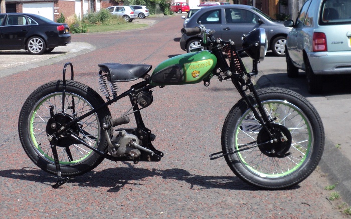
It’s offered up and becomes immediately obvious that the front wheel has to come out, so it’s a case of lift the front end of the bike up onto the front stand and drop the wheel out.

The guard mounts onto a lug under the lower yoke of the main girder of the fork, I try mount the guard with a 1/4 bolt and promptly realise that it needs a 5/16 so it’s go and get the other bolts and realise that I’ve only a limited supply of 5/16.

Anyway there’s one that’s right for the bridge mount so I go to fit it.

It won’t go in!. Turns out that both the lugs on the mudguard and on the fork are clogged with paint so remove that and the mudguard is mounted onto thefront fork for the first time in over 20 years.

The front stays are bolted in place after running a tap through  the fork mounts but when I go to attach the front stand it does not align with the brackets on the guard, I think that over the years it was unmounted the guard has relaxed a bit and is now a greater radius than it was originally.

I now have 2 options, either make up new, longer mounts or try to strain the guard back into the original curve, I suspect that the first course will be the easier.

Before doing that though we’ll get the back mudguard fitted.

This offers up into place easily, then I realise that I can’t get my fingers between the tyre and the guard to fit the nuts in place.

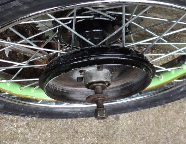
So now it’s the back wheel that has to come out!

Turns out that this guard has relaxed a bit as well!

However I bolt the front lower mount in place and then the rear stays-come-grab handle.

This leaves the centre mount, onto the seat bracket, about an inch clear of the guard.

I grab hold of the grab handle and pull it towards the front of the bike and the guard and the seat bracket promptly align.

A webbing strap was then put between the grab handle and the main frame and used to strain the guard into place and the seat bracket/mudguard bolt fitted.

Last thing for the day was to fit the stand spring so the lower end was hooked onto the stand leg a cord fixed round the upper one and it was stretched into place.

One of the Murphy Laws now came into force because as soon as I took the bike of its stand I realised from the way that it fouled the frame that I had fitted the spring upside-down.

So, back up onto the stand, remove the spring and reverse it.

Easier to say than to do! and this time the spring was clear!

Time for a Change

Now that the frame is up onto its wheels its time start to hang bits on it.

While at first sight I want the mudguards on next, in fact it makes more sense to fit the gearbox first, so that’s the next job.

So it’s disinter the gearbox from the back of the garage, get the Gunk out and clean the old crud off it.

Straight away I spot that the kickstart spring has broken, I’d forgotten about that!.

Anyway with a Burman gearbox it’s easier to work on it in the frame than on the bench so it’s on with the job.

This bike uses the older adjustment method where the gearbox pivots on its bottom mounting bolt and primary chain adjustment is with snail cams on the top mounting bolt.

So its drop the box into the frame and slide the bottom bolt into place without the spacers between the box and the engine plates.

Next swing the box so the top bolt can be slid into place to locate everything and then slip one of the spacers into place between the gearbox top mount and the engine plate.

As everything has to be a neat fit the other spacer won’t, quite,  go into place.

So it’s a case of wedging the engine plates a little further apart until the spacer will push into place and once it has been fitted slide the mounting bolt into place and fit the snail cams onto that bolt.

It’s not tightened up yet though as the spacers still have to be fitted to the lower bolt so it matches the top one.

Now I find that the new battery mount plate I had made does not fit properly, it will foul the rear mudguard and is fouling the top of the gearbox so that has to come off to be “adjusted”.

Since the bikes now on its wheels with the gearbox in place I decided to put the tank on to get an idea of what she’s going to look like.

M100

As is today

Suddenly its a bike again rather than just an assemblage of parts.

=====================================

As a “By The Way”, at the weekend I went to Helmsley Steam Fair.

It proved to be a Vintage Transport Extravaganza and I have posted some photos on my Flickr site at :- http://www.flickr.com/photos/drewgrant/>

They are also up as a set at:-

<http://www.flickr.com/photos/drewgrant/sets/72157634555939192/>

Baby’s got new shoes

In the last note  I said that I’d fitted a set of tyres onto the wheels.

Well I’ve now gone a stage further and have fitted those wheels back into the frame.
new shoesfitted

Starting to look right

Needless to say it was not as straight-forward as that since I had to sort out the spacers to get the wheels where they should be in the frame.

Then I had the back wheel in and tightened up when I realised that the brake anchor arm was not on its peg, comment of “Oh Dear!”, remove the wheel again and refit it.

Then the sprocket bolts were fouling then frame. (The sprocket has been re-toothed by turning off the old teeth and bolting on a new set of teeth).

So it’s out with the wheel again, remove the sprocket and refit the wheel once more.

This time the wheel would spin ok but there’s something just catching inside the brake assembly as when you spin the wheel you get a “tick – tick – tick” as it turns but I’ll leave that for now.

With the frame up on its wheels now the feeling is that the back of the job has been broken and I’m now on the downhill run to completion.

A Cushy Number

Now that the rear wheel has been rebuilt it’s time to refit the brake drum and the sprocket.
When this old lady was built Panther, among others,  were using a rear wheel assembly they bought in from Royal Enfield.
This hub had a separate, bolted on, brake drum on one side of the hub as well as a rubber block cushion drive shock absorber built into the sprocket assembly on the other.
The brake drum is simply bolted onto a spigot on the right-hand side of the wheel, nothing fancy although the drum does have a re-inforcing rib or fin cast onto its exterior to strengthen it and help prevent the drum from “belling” under heavy braking.

Rear Brake Drum

Rear Brake Drum

The re-assembly of the sprocket cush drive is a bit trickier.
This consists of a set of six rubber blocks in the hub housing with a cast rib going between every other pair.

Cush Drive

Cush Drive and Rubbers

The sprocket has a similar set of three ribs that go in between the other blocks so that any snatching in the drive is cushioned.

Sprocket & Hub

Rear Sprocket & Housing


This same system is still in use to give a smoother drive on many more modern motorcycles including some in current production.

When assembling the drive, if you just put the rubber blocks into their place and then try to fit the sprocket it just won’t go.

"tented" blocks

“tented” blocks

Trick is to “tent” the blocks and then the sprocket will readily push home.
As with everything a little lubrication works wonders and the lubricant of choice here is french chalk or talc.
I put the rubbers into a plastic bag and added a generous measure of talc, closed the bag and gave a good shake up.
This coated the blocks in talc and left them with a slippery surface. I put them in place, tented, dusted the sprockets drive ribs with talc and then pressed it into place.

Assembled Drive

Assembled Drive

You can also see here a useful trick for when you have to work on a wheel with a fixed axle, use the car’s spare wheel as a support. This means the wheel is stable rather than being balanced on the rim and the axle, and it is supported by the car tyre rather than a hard surface.

 
One point not mentioned yet is that the sprocket must be able to twist on its central mounting boss so this needs to be greased before fitting the sprocket into place.
There is a later version of this hub with the brake drum and sprocket in one assembly and Panther changed over onto using this hub in later years.
Just to be awkward it not only uses smaller and differently shaped rubber blocks but the brake assembly internals are different and this hub will not fit in place of the earlier unit.

 
As you can see the old lady now has a set of new shoes in that there are now tyres on her wheels.

New Shoes

The New Shoes

As soon as there is space in the garage I’ll bring the frame down from the workshop and fit the wheels to it, I’ve currently an ongoing job on the sidecar outfit in there in what is earmarked as the Panther’s space.
I’ll then have an incomplete bike rather than a set of parts, a major step forward on the road to a complete bike.

Situation update

Just to keep folk up to date.

I’ve not added anything lately because it’s just been more of the same.

The rear wheel rim has had its centre rubbed down and  painted, same as was done for the front and has been at the wheelbuilder, I just got it back yesterday, so tomorrow I’ll order up a pair of tyres, tubes and rim-tapes for the old lady, then comes the fun of fitting the tyres and once that’s done I’ll have a rolling chassis to work on.

That’s going to push me into getting the mechanicals finished and fitted and will be when I begin to find out what’s been misplaced over the years she’s been standing.

With the motor I’ve got the new piston rings gapped and the barrel has been cleaned externally with wire brushes

Donkey work was with a simple “scratch” wire brush that cleaned the barrel-base and down to its wall between the fins.

To clean the fins themselves I used a 1/4 inch diameter tube-brush, think of a bottle-brush but with wire bristles. These are available in a number of sizes, with either steel- or brass-wire bristles.

I got mine through Cromwell Tools who have branches around the UK, I usually just go down to the local branch but for these brushes I had to put them on order and I got them the next day but they also have a web presence and web shop The “Savers” in their “Interactive e-Brochures” is usually worth a look at and is updated monthly.

Once I had the barrel clean it was swabbed with white spirit to clean off any grease and then dried and put into the oven on low heat for 10 minutes.

It was then taken out and sprayed over with black “Smoothrite” and then put back into the oven for another 10 minutes before being given another coat.

Result is a satin gloss finish on the barrel and all it needs now is the glaze on the insidew of the bore “breaking” before it is fitted onto the piston and new rings.

As the cylinder head is also cast iron it’s now on the list for the same treatment.

The Mechanicals.(2)

While I do not intend to split the crankcases of the engine they sadly need cleaning and to help with this I’m going to remove the timing case cover so I can clean it up separately and then paint the raised “Redwing” logo on it.

The cover is held on by three nuts which are on studs going through both crankcase halves and nine raised countersink head screws.

All of the screw heads have the slots damaged but with care and pressing the screwdriver blade hard into each slot as I unscrewed them I managed to get them all out.

To my surprise they are threaded 1/4inch BSW, I’d expected them to be either BSCy or BSF.

The old Whitworth thread is seldom found on vehicles as it is so coarse. The finer pitch BSF (British Standard Fine) thread is much more common, and on most older British made bikes the BSCy (British Standard Cycle, sometimes also called CEI or Cycle Engineers Institute) threads are often used.

However Whitworth is the strongest of the thread forms so I suppose its use in threads going into the aluminium alloy crankcase is not too surprising.

Fortunately all these thread-forms use the same range of spanners, and this brings up a frequent cause for confusion for newcomer owners of these elderly machines, they can see no relationship between the size marked on a spanner and the size of the nut that it fits,the fact that each spanner is marked as being for two different sizes adds to their problems.

The relationship becomes obvious when you realise that the sizes are specified on the stem diameter of the bolt in question, so a 3/4inch Whitworth bolt is 3/4 of an inch in diameter, but a 3/4inch Whitworth spanner is 1.300 inches “across the flats” as that is the size specified for a nut to fit a 3/4inch bolt.

A 3/4inch Whitworth spanner is of such a length that it is difficult to get enough pressure on the bolt to strip the thread. Since BSF is a finer thread than BSW it is easier to strip so a 3/4inch BSW spanner also fits a 7/8inch BSF nut and is the correct length for it.

In the Unified and Metric thread-forms the size stamped onto the spanner is the across the flats dimension of that spanner, so the system is specified on the size of the spanners used rather than on the bolt size. If you like one system is specified by the designer and the other is specified by the repair-man.

On removing the timing cover some thick, black, oily gunge dribbled out so I’m going to get some paraffin and clean out the insides of the timing case before I re-assemble things.

When I had a look at the timing cover I found that while the old gasket was intact, there were traces of an older gasket still on the crankcase joint face, this is the main reason why old Brit bikes have a reputation for being oil-leakers, it’s not so much the bikes at fault as the owners
making basic mistakes such as this so that the joint faces to not pull together properly, a tiny gap is left and the hot oil finds its way out.

Inside Timing Cover

Inside Timing Cover

Anyway, I’ve put a set of case screws onto the list for the next lot of spares ordered.

Then it was just set to with hot soapy water and scouring pad to clean up the outside of the timing cover.

Timing Cover

Outer appearance of timing cover

It appears to be cast from an alloy that has a relatively dark colour as while it has cleaned up quite well it does not have the bright silvery appearance of the casings on a more modern machine.

The Mechanicals.(1)

So far everything has been working on the running gear but that’s not all there is to do, the engine and transmission are still to start doing.

The engine has been on the bench for a while and it’s time to make a start on it.

The bottom end was sound when the bike was taken off the road so we’ll leave that alone.

There’s a choice of three barrels for her, one has a broken fin but the bore is only a little worn, however there are only two use-able rings on the piston, the middle ring being broken.

Another has sound finning but has been subject to a mild seizure, the bore is about half-worn and there are marks of the pick-up on both the piston and the bore. It’s only been a mild seizure however as the pick-up marks are light and the rings are free with no sign of smearing of the ring lands while the third barrel has sound finning but has the rings seized into piston lands.

All in all I’m going to use the first barrel but fit a full set of new piston rings after “breaking” the glaze on the cylinder bore, the idea of having one of the other barrels bored to suit that piston is a non-starter since that piston is standard size and both other barrels are over-size.

I’ve managed to find a set of new piston rings for it so next thing is to gap those rings and then to fit them.

An oddity that has turned up however is that the bike uses a slipper piston, something you’d only expect to find on a higher performance machine!

Slipper Piston

This is a slipper piston. (It is the piston with the seized rings)

Before fitting the barrel I’ll need to black it, what I’ve successfully done before this on side-valve barrels is to get the barrel clean and then spray it with “Smoothrite” black. The barrel is then oven-baked for an hour on low heat, there are certain advantages to the wife being away!

Then it’s given a second coat and the treatment repeated. This gives a durable, semi-gloss appearance and the only place it has not lasted has been on the exhaust port finning so it should be ideal for the OHV Panther barrel.

Front Wheel (2)

Once the rim had been prepared it and the new painted hub were taken back to John at North East Wheelbuilders to be built up into a complete wheel.

A little over a week later I received a call to tell me it was ready to pick up so it was back to John’s to collect it.

Job now was to apply the coachlines around the painted centre of the rim.

A couple of 4 inch lengths of 2 inch square timber were sorted out and a groove and a hole were made in both.

This allowed me to place the wheel between the open jaws of the Workmate with the axle resting on either jaw. The timbers were then placed with the groove over the axle and a bolt passed through both the hole and one of the holes in the Workmate’s top and the timber pulled down tight onto the top of the Workmate.

Now it was a simple job to place a paint-laden lining brush against the rim and gently turn it so as to leave the required coachline on both sides of the wheel.

Once the lines had dried out a coat of laquer was applied over them.

All that was needed now was to fit a tyre and tube.

According to the book, a 1937 Model 100 Panther wears a 3.25 x 19 inch tyre front and rear.

First thought was an Avon Speedmaster on the front and an SM MkII on the rear. Further thought said to fit an SM both front and rear as I intend to use this girl both as a solo and hauling the Steib S350 I currently have on the R12 and the Speedmaster is not a good tyre for the front of an outfit.

Problem arose on checking the websites when I found that the SM is no longer available as a  3.25 x 19.

I found that I could get a Mitas tyre, intended for front or rear fitment, on which a package deal was offered of tyre, rim-tape and inner-tube so it was a case of order it up and await delivery.

Last thing was to sort out the speedo drive.

Unlike more modern bikes this is taken from a gear-wheel threaded onto the bearing boss in the front brake hub.

This meshes with a gear on a right-angle drive that screws into a socket on the front brakes backplate.

First thing was to fit the new gear-wheel I’d got from the Owners Cub spares scheme.

This has an internal thread which matches the one on the outside of the bearing boss.

Now the old gear had been removed back when I started this rebuild in the 1980‘s and the  thread on the boss was gummed up with it having been taped over when I sprayed the hub so I wasn’t too surprised when I couldn’t get the thread to start, so it was down to clean out the thread with solvent and small “toothbrush” type wire brush.

It still wouldn’t pick up the thread, I must have spent a good quarter hour cleaning and re-cleaning the fine pitch threads on the boss and the gear when suddenly light broke through!.

The brake-plate and so the drive are on the right-hand side of the bike. This means that the drag from the drive would tend to unscrew the gear from the hub!

So I tried it the other way and the thread picked up straight away. It was a Left-hand thread!
I could have kicked myself for not realising it sooner.

Then it was just a case of measuring how far the gear-wheel was in from the brake-plate and screwing the right-angle drive box far enough into its socket to get the gears to mesh properly and the job was done and the wheel ready to fit.

Instruments (2)

With the front wheel away being built-up I decided it was time to sort out the speedometer drive.

This is taken from a big gear-wheel mounted on the brake-side front wheel bearing housing with a right-angle drive gearbox, similar to those used for a rev-counter drive.

First thing was the big gear, spec. for the Panther is a 44-tooth gear on the wheel mated to a 14-tooth gear on the drive box so I had a rake around in the “stores”.

First thing was the drive-box gear and I found that I had a pristine 14-tooth gear in stock, ideal!.

Then I found 4 of the big gears. While one was damaged beyond use the other three were more than usable, BUT! On doing a tooth count I found that while the damaged gear was a 44-toother, all three of the decent ones had only 43 teeth! Typical!!.

A swift check of the POC spares list showed the correct gear in stock though so that’s something else added to the list.

Then it was have a look at the right-angle drive.

There were three of these in the “stores”.

On inspection two were damaged and one seemed good.

The good one spun easily and there seemed no excess play on the output shaft so that was the problem solved, or was it!.

On a trial assembly it turned out that the drive-box output shaft was spinning anti-clockwise and, of course, the speedo head demands a clockwise input.

I then went to look at the other two ‘boxes and found that while the first box did have a clockwise output, the problem was that the output housing had the threads broken off so there was no way to connect a drive cable to it, not only that but it was very stiff to turn over and there was a lot of play at the output shaft, the output bushing was gone!

A look at the other and things got worse!.

The threaded input housing that it mounts by (it is screwed into a housing on the front brake plate) was totally stripped. Then just for a bonus on this box, it was seized solid and on closer inspection I determined that the input housing was bent.

So – “What to do?”. I got in touch with the company who had rebuilt the speedo-head and they put me in touch with a real “Name From the Past”, A Gagg and Sons! (I thought they’d closed down years ago!).

Yes they are still trading, but they have cut back to specialise in just Smiths speedos and rev-counters.

I had words with them over the ‘phone and it emerged that the “good” drive was probably from an ex-WD 16H Norton, given the paint finish on the box and the fact that the cover cap for the input shaft was painted red.

While they thought there was one “on the shelf” they offered to rebuild mine and reverse the drive for half the price of a new one, so I of course took up the offer! (Hey Panthers were made in Yorkshire remember, and you know what they say about Tykes, “Short arms and deep pockets!”. Not only that but I’m a Jock!, got a reputation to keep up you know.)

I sent all three boxes down to them in last Thursdays post and received a ‘phone call from them at lunch-time today, the following Tuesday, to say the job was done, and as they had
been able to use some parts from the other boxes it would be £20 cheaper than their quote, Even better! and you can’t ask for a better turn-round time on a repair than that.

Tank Attack, Final Phase

Once the paint on the tank had been given time to cure it was a case of masking the edges of the panel with a narrow tape that would follow the curve that I wanted.

After I had the panels outlined with the narrow tape I then masked off the rest of the panel so that when the dark green was sprayed onto the main body of the tank it would not get onto the light coloured area of the panel.

The rest of the tank was then rubbed down with 400 grit wet & dry paper so that there was a good keyed surface for the top coat and two coats of the dark green sprayed on.

The second coat was given 15 minutes to start to cure and then the masking was stripped off the tank.

Reason for this is that as the paint is still soft, stripping the masking tape off will not leave a chipped edge on the new paint, also the edges should still be able to flow a little and will then leave a softer edge between the main tank colour and the panel.

Painted Tank

Painted Tank

The tank was then left for a couple of days to cure and it was then gone over with polishing compound to rub down any minor irregularities and to give a gloss finish, then a layer of laquer was applied.

Now the tank had to have the coachlines added.

Traditionally this is done freehand using a special lining brush and it needs a steady hand and a deal of practice to be able to do this.

Fortunately there is away round it. You can get a special lining tape where there is a backing tape carrying two strips of masking tape the required distance apart.

You put this in place where you want the coachline, strip of the backing tape to leave the masking tapes and then carefully paint in between those tapes, strip the tapes off and there’s your coachline.

Tank p4epared for coachlining

Tank prepared for coachlining

Sounds easier than it in fact is as it is fiddly getting the backing tape positioned round a curve, it will take a bend but the tighter the bend the more awkward it is to get the tapes to lay flat and keep a constant line width but with a bit of time and patience you can get a good result. The extra pieces of tape at the rear corners are to give a “run off” so that I could take the paint to the end of the lines without worrying about over-running.

The tape is an American product, called “Finesse Lining Tape” and there is a choice of tapes to give various widths of line, it is also supplied to give double lines if you need them. Their UK agent is A.S.Handover and you can Click here for  a direct link to their catalogue pages of these tapes, not only that but they can supply you with  signwriters paint to make the lines with and even the pukka coachlining brushes if you wish to try the traditional way.

Once the tank had been lined I applied the transfers (or decals if you prefer the expression) and it was left it to dry for a while.

The whole thing was then given a couple of coats of laquer to seal everything and that was that.

Finished Tank

Finished Tank

I got the transfers from the Vintage Club’s transfer scheme who have transfers for over 350 makes. Click here to go to their site.