Category Archives: Panther

Panther motorcycle restoration

A Bit of Hush

The new pipes and silencers have just been delivered, it took a while after they were ordered last month only to find the pipes were on back-order.

I’d no sooner received them than I went to fit the new pipes.

These have a flanged end that is clamped against the end of the head stubs by a big ring-nut and there needs  to be a gasket between the pipe and the head to seal the joint.

The originals would have been a copper/asbestos crush-ring but these are no longer available, however there are useable substitutes around as a number of modern engines also use this system and their gaskets will fit.

The trick when fitting these is to get the pipes flange flat against the head stub and nip it up like that.

To do this you fit the pipe loose and on it own, before securing the lower end. If you try to fit it with the far end secured to the silencer then the flange is guaranteed to sit with one side against the  stub  and the other tilted over and not in contact with the stub. Once it is like this you will never manage to pull the flange into a decent gas-tight joint with the stub.

So it’s slip the ring nut over the pipe, put the gasket in place and offer the end of the pipe up to the exhaust stub on the head.

This is one of those jobs you really need two pairs of hands for, but a helper gets in the way!

You need to support the length of the pipe, align the end against the end of the stub while keeping the gasket in place and then persuade the nut to start on the threads of the stub while not to cross-threading it.

Then after I’d managed this and wound the joint up to hand tight I realised that I had the pipe on the wrong side of the footrest, so I had to take it off and start again, to mutterings of “Oh what a joyous thing to have done!” and like imprecations :).

Anyway I managed to get it back together again and then went and fitted its mate on the other side, for all that the Panther is a single cylinder machine it has a twin port head and so has a double exhaust system.

There was a fashion for these back in the 1930’s with most of the manufacturers having them in their line-up but Panther kept supplying them as standard to the end of production, the last of the line as it were.

Panther claimed that under heavy use, such as when pulling a sidecar, the twin-port head was less liable to warping than a single port, I don’t know the truth of this but I do know that back in the old days of the 50’s and 60’s it was not unknown for an impecunious owner to blank of one port and run on a single pipe and silencer.

Come to that you could order a new Panther from the works with a single-port head as an option.

Next job was to fit the silencers.

These have a loose “P” shaped clamp-on bracket to mount them onto the bike and I’d ordered up a new pair as well since I only had one old one and that was home made.

The clamps that came up were for “Universal Fitting” and so had to be atered to suit.

I had to fit the clamp onto the silencer, then mount the silencer onto the pipe and line up the clamp with the frame attachment point and mark the fixing point on the clamp.

Then it was take the clamp off, centre pop the mounting point and drill it to suit.

However the mounting “tongue” of the clamp was too long it also had to be cut back to suit and the ragged end from the saw-cut dressed of smooth and neat.

Last thing but one was  to refit the clamp onto the silencer and bolt it up to the frame.

Panther right

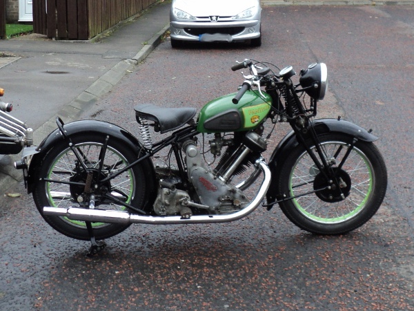
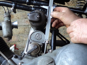
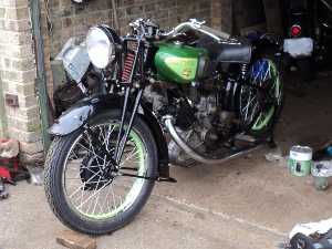
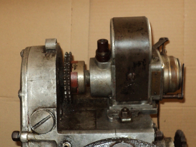
Timing Side, nearly complete.


Panther left

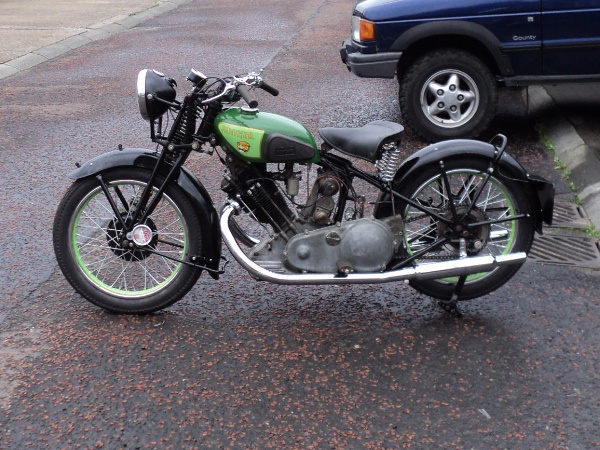
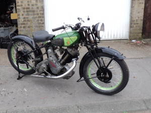
Drive Side, nearly complete.

Last of all was that the manufacturer had put an adhesive sticker onto each pipe and silencer.

Because these were plastic, rather than have them melt and burn onto the pipes I had to remove them, and they would not just peel off.

I wound up heating them up with a hot-air gun until the pipe was uncomfortably hot to touch when they, reluctantly, peeled off leaving a layer of adhesive behind.

Then it was rub with a cloth dipped in WD40 to finally remove the adhesive layer, and even that took a bit of doing.

I wound up spending nearly as long cleaning off the stickers etc as in fitting the pipes!.

A Bit On The Side

The big Panthers are best known as sidecar bikes, back in the 1950’s and 1960’s it was very rare to see one being ridden solo, they normally were seen hitched to a big saloon sidecar such as a Busmar or a Carmobile and they were in fact normally sold as an outfit.

I intend to run mine both as a solo and with a sidecar so I need a sidecar and rather than a big saloon chair I’ve a nice little open sports job that’s based on the Steib S350.

Sidecar 1

This is a copy of an S350 Steib on an LS200 chassis

Sidecar 2

It’s in quite nice condition but is a right-hooker.

As you can see it’s not in bad condition but a new seat is required. There is one with it but while it is usable it is too bulky and is a poor copy of the original.

A problem is going to come up with fitting it because as you can see it is meant for fitting on the right side of the bike while in UK a sidecar is normally fitted on the left.

The sidecar is mounted on a Steib LS200 chassis which uses the German DIN standard sidecar fittings and it will mean sourcing a set of bike-side fittings to suit and will probably need a sub-frame to pick-up to that front mounting-point on the chassis.

Besides that the DIN fittings have the beauty that using them means that you have a sidecar that is both quick and easy to remove from the bike, not only that but you do not lose the sidecar alignment settings when you remove it, so when refitting the sidecar you do not need to re-align it.

However, a disadvantage of the LS200 chassis is that it only has a three-point mounting.

While this is adequate for on the smaller bikes (sub-350ccs) that the LS200 was intended for, on a more powerful machine it is better to have the more rigid four-point mounting and it will be necessary to arrange for this.

So, – –   Why fit a sidecar?.

Well it means that I can take the bairns with me when I go on events, it gives me extra carrying capacity for luggage and so on, and quite simply, I like them.

Riding a sidecar is totally different to riding a solo, it means learning a new and totally different set of skills but once you can handle an outfit they are great fun to ride, not only that they are great attention getters.

On Tap

Another problem that arose was with the fuel tap.

Panther only provided mounting for a single tap in the tank, with a balance pipe between the two sides so that you did not wind up with the tap side of the tank dry and fuel trapped on the other.

This does mean however that, unless you have a fuel tap with a built in reserve function, when you run out of fuel you will wind up pushing the bike. A Panther is a heavy machine to push, not only that but the nearest fuel is always in the opposite direction to the one you are pushing!.

To further complicate things, rather than use the common tank outlet size of 1/4 inch BSP they opted to use the rarer 1/8 inch BSP size, (you should realise here that with the pipe thread sizes, (British Standard Pipe) the dimension refers to the bore of the pipe and not the OD of the thread) it so happens that with this design of tap there is no difference in the internal bore of the actual tap with either size.

The tap I had was the common ENOTS hexagonal body type and it did have a reserve, but this was seized so I went looking for a replacement.

Tap

The seized fuel tap

I found a number of sources which listed this tap in both 1/8 and 1/4 inch sizes but when I tried to order one I was informed by them all that the 1/8inch size was “out of stock” and they had no idea when they would get any in, but they could supply the 1/8 inch size tap without a reserve.

So, nothing ventured nothing gained, I decided to try to strip the seized tap and clear it.

Tap2

Dis-assembled fuel tap.
The cork sealing disks are below the main tap body

As you can see the tap splits into three major parts, the top section, which contains the reserve mechanism, the centre which has the “On – Off” slide and the lower section which connects to the fuel line. The taps seals are the two disks of cork, each with a central hole, which are compressed one against either side of the centre’s slide by the other two sections.

There was no immediately obvious way for the reserve to come apart but as there was obviously an inner sleeve and an outer I decided to try a little pressure against the projecting end of the inner.

A suitably sized socket was placed at the lower end and the tap and socket nipped together in a vice.

Tap3

Tap being pressed apart

Given steady pressure the inner sleeve began to slip down into the outer, so it was pressed down until it was flush and then removed from the vice.

For all it had come most of the way through, the inner section still would not simply pull out using my fingers and since I did not want to damage the sleeve surface with grips I used a pin punch to knock it the rest of the way through.

Once it was apart the reason why it would not move was obvious in that the brass insert was blackened with corrosion but at least it was not pitted.

I polished it clean with a fine grade of wet and dry paper and then re-assembled the two sleeves and found that the reserve function was now working without problem so they were again disassembled.

Tap4

Tap with reserve stripped

As I had a pair of new corks for the tap, before fitting them they were soaked in  boiling water for a half hour to soften them.

The reserve sleeve was then wiped with silicone grease and whole tap then re-assembled with the new corks in the main body and I had a functional reserve tap for use on the old lady.

Sod’s Law Strikes

While the gearbox was out of the frame for new bearings I fitted the battery platform to the bike.

As I did not have one originally, this is a scratch built thing based on photographs.

It sits between the seat tubes, above the gearbox and is held in place by the four bolts securing the seat tubes to the engine plates so while the gearbox was out was the ideal opportunity to fit it due to easy access to these bolts.

Once the gearbox was finished it was refitted in the frame, as was the rear mudguard and everything was looking good.

Next step was to fit the primary drive chaincase. The rear half of this is held in place by one of the nearside seat tube bolts and by a second set screw going into a boss on the crankcase.

So the rear half of the case was offered up and went into place nicely, both mounting bolts lining up as they should so I started to tighten them down – – –  and immediately ran into trouble!.

The problem was that the new battery platform was fouling the back of the chaincase!

It wasn’t by much and I could have pulled the case home into place BUT I would not have been able to mount the battery securing post on that side.

After a few comments along the lines of “Oh dear!” and “What a thing to happen!” I settled down and took a careful look at things.

Whereas at first sight I had thought I would have to remove the rear mudguard and the gearbox again just to gain access I realised that by taking the magneto off the motor and working through the slot left for the clutch cable to go through I probably could get the battery platform off, but to do this I had to remove the primary chaincase again.

The effort proved successful and I modified the carrier to give the necessary clearance, not even a 10-minute job.

Now came refitting it, using tweezers to fit the washers onto the bolts through the cable slot and wangling the nut on using a screwdriver in one hand holding the nut against a finger of the other to get it in place, holding it there with the finger tip and turning the bolt head with the other hand until the thread caught.

Finally, aided by a little creative use of language, I had the platform back in place and when the chaincase was put in place there was clearance as required, all it means is that the battery will not now be sitting central over the engine plates.

As I had the back of the primary case in place now I took the chance and fitted the clutch assembly in place before calling it a day.

Bearing Up

Now that the new bearings have arrived it’s time to fit them.

Steel bearings into an alloy casing- -that means heat the casing to expand it.

The alloy expands more than the steel so by heating the case the old bearings will drop out and the new ones can be dropped in.

So it’s into the kitchen with a piece of plywood to protect the work top, some shop-rags, the new bearings and the inner and main casings.

I’ve already extracted the studs from the casings so they will sit square on their faces on the plywood  and the new bearings are unwrapped and put ready to hand.

The first casing is put into the oven, 10 minutes at Gas Mark 7 gets it hot enough that when a moistened rag is rubbed across it it sizzles so it’s taken out of the oven(GLOVES!) and rapped square and flat, open end of the bearing cup down, onto the plywood and the old bearing just drops out.

Smartly turn the casing over so it’s sitting open end up on the plywood, wipe the bearing mount clean with the shop-rag, drop the new bearing into place and then weight the bearing down to make sure it stays hard home in the casing as it cools and that’s the job done.

The second casing is now put in the oven. By the time that it has heated up the other casing has cooled enough to grip its bearing firmly and so it can now be put to one side and the whole process repeated with the second casing and bearing.

While the second case is cooling you have time to remove any evidence of your use of the oven from the eyes of S.W.M.B.O. and then get the casings etc. back into the workshop.

G/box Contents

Set out for re-assembly

Each of the bearings is held in place by a circlip and these pop easily back into place so the bearings are fully home in their housings.

Next thing is to install the output gear into the output bearing. This is a tight fit so it needs to be pressed home, easy answer is to pop over to Bob’s and use his press rather than codge up something, so with that gear now in place it’s time to rebuild the ‘box.

The gear cluster is assembled with the selector assembly meshed in on it and the whole lot offered up to the main casing, a little wangling and the layshaft end slips into its bushing, the end of the camshaft does likewise and the whole assembly slides into place.

The mainshaft is quickly slid into place through the output gear to lock things in place, the first gear pinion slid onto its end and that’s it.

main case

Gear cluster in place

All that’s left to do is fit the indexing pawl in place, put the bearing rollers in place on the cam-shaft and the inner casing can be put on and bolted up.

inner case

Inner casing bolted on

Once the inner case is in place then all that’s left to do is to fit the kickstart ratchet, match up the timing marks on the cam-shaft and the gear-change mechanism, wind up the return spring on the kickstart shaft and then fit the outer case with the foot levers and the rebuild is finished.

Bearings Down

I’ve known from the start that the kickstart return spring was broken, but otherwise the gearbox seemed OK, it was selecting gears and turning over in all four gears smoothly, with no roughness of feel to indicate a bad bearing.

I got a new return spring at the weekend and so went to fit it. As this is a grease-lubricated gearbox I could not just take out the drain plug and empty it before I started so I expected a bit of a mess but last night I broke the seal around the outer cover of the case and left it to drip overnight.

BGearbox

The Gearbox

This was more succesful than I expected as when I took the outer case off completely this morning there wasn’t that much grease left in the ‘box and a fair bit of gloop in the catch pan, I suspect it may have been filled with a 50/50 mix of grease and oil, a not uncommon trick back in the day.

Open Gearbox


With Outer Cover Removed

It quickly became obvious that the kickstart spring had broken, about 2 turns from its inner end, so I removed the kickstart lever from its shaft and then the quadrant from the case.

I had an old 5 litre oil can with the side cut out and with about a litre of paraffin (kerosene) in it, along with a paint brush and a couple of toothbrushes (Sainsbury’s cheapo’s at 18p a pair) and used them all to wash out the outer case.

Dismantled controls

Dismantled contents of kickstart case

Once I’d replaced the spring I decided to check its meshing gear and the kickstart ratchet for wear so I undid the nut on the end of the mainshaft and removed them. While doing this I noticed that the mainshaft bearing “looked wrong” and on closer examination found it was frozen, with the mainshaft turning in it, the mainshaft is intentionally a slip fit in the bearing.

Swift replan of things!, the gearbox had to be stripped.

In theory the bearing can be replaced on its own without this but it’s not a good idea to replace only one of a bearing pair, and it’s a total gearbox strip to do the drive end bearing.

According to the book you remove three nuts and the inner case will simply slide off along the studs,

So says the book but needless to say this did not happen and the inner case had to be wangled along a bit and then the gears pushed back into the main casing before the inner case could be finally wangled off.

In these Burman ‘boxes the selector camshaft runs in a crowded roller bearing in the inner case and when that case is removed the rollers promptly drop onto the floor and are lost, but I knew about this little”feature” and so had put a large cardboard tray under the gearbox to catch them as they fell.

Once the sticky mass of grease in the tray was checked through there they were, 11 little rollers, but there should be 12 of them!. So check the gearbox shells and shafts, No, check the floor, No, no sign anywhere.

So next was to take out the gears as a set, first remove the mainshaft itself through the primary chaincase, remove the indexing pawl from against the camshaft and the whole cluster just lifts out.

Check the gears, even between their teeth, still no sign of the missing roller but the gears are bright clean without any sign of corrosion and, while used are still eminently serviceable. The mainshaft shows no scuffing or other wear where it runs in the bearing at the kickstart end so it cannot have been running in the bearing, which must have frozen with standing for so long and not when last in use.

All that’s left to do is to take the shell out of the bike to replace the drive side bearing, while it is possible to do it “in situ” I want to clean the case out completely.

Easy way here is remove the rear mudguard and drop the shell out to the rear, and as I have a couple of jobs to do on the rear guard anyway it will kill two birds with one stone as it were.

On checking the lists both bearings, as well as new camshaft rollers, are available through the Panther Club so I’ll order them up.

Under the Wire

You control the various systems of a motorcycle through Bowden cables,‭ ‬a crafty way to transmit a push-pull action through a flexible cable.‭

Where you have a modern machine you can just walk into the dealers and buy a replacement cable over the counter but Panther ceased manufacture back in the‭ ‬1960‭’‬s so this option is not available to me.

Since I require a full set of cables for the bike I am going to have to make up my own from scratch.‭

You can buy so-called‭ “‬universal‭” ‬cables.‭ ‬These have one end already made up for you,‭ ‬what you need to do is cut the cable to length and then either use a solderless nipple or solder one of the the loose nipples supplied in the kit onto the free end of the inner wire.

These‭ ‬cables cost around‭ ‬£11:00‭ ‬each however and there are a total of eight cables on the bike.

All of the various components are available however, from a number of sources and at a‭ ‬noticeable cost saving . ‬I’m getting them from Vehicle Wiring Components‭ since I’m also using them for the wiring and associated electrical parts I need.

DSC1047
Cable components and cable cutters

A complete cable consists of an outer casing,‭ ‬an inner wire,‭ ‬a pair of ferrules,‭ ‬an adjuster and a pair of cable nipples.
The casing comes in a range of sizes‭ ‬varying from the very light‭ “‬No.‭ ‬0‭” ‬used for bicycle gear controls to the very heavy‭ “‬No.‭ ‬5‭” ‬used for car hand-brakes and trailer brakes,‭ ‬on a motorcycle normal use is‭ “‬No.‭ ‬1‭” ‬for the throttle and‭ ‬other light-duty controls and‭ “‬No.‭ ‬3‭” ‬for the front brake and clutch.

There are,‭ ‬of course,‭ ‬a similar series of inner wires associated with these casings,‭ ‬along with the appropriate sized ferrules and a range of adjusters and nipples to suit the various controlled mechanisms.

What I’m making up here is a magneto‭ (‬or ignition‭) ‬advance/retard cable which uses a No.1‭ ‬casing.

First thing to do is to see what nipples are required for the cable,‭ ‬in this case I need two‭ “‬drum‭” ‬type nipples,‭ ‬each‭ ‬1/4‭ ‬inch in diameter by‭ ‬1/4inch thick.

Next is to measure the length of casing required so I’ll screw the adjuster‭ ‬into its mount and run the casing up to the handlebar lever,‭ ‬making sure there are no tight bends and there is enough slack for the handlebars to turn.‭

Once I have the correct length the casing is cut to suit.

Because the casing is basicly a spring with the coils touching each other the while it can bend its overall length will stay the same.

Once it has been cut to length you often find that the cut end of the casing will partly block the centre bore intended for the inner wire,‭ ‬so the two ends of the casing will need to be dressed off square and then a ferrule fitted to each end,‭ ‬I secure them with a dab of‭ “‬Super Glue‭”‬.

The inner wire needs to be same length as the casing PLUS the extra needed to reach the nipple sockets on the lever and the magneto so theseadditional lengths need to be measured.‭ ‬When cable lengths are quoted the convention is to work to the‭ “‬pull‭” ‬side of the nipple so if you have a‭ “‬book figure‭” ‬for the cable lengths you need to‭ ‬remember to allow for the short lengths inside the nipples,‭ ‬in a‭ “‬worst case‭” ‬you could have an inner cable a half-inch too short if you don’t‭!‬.

measure
Measuring distance between adjuster and lever

Once the length needed is known then you need to cut the inner wire to length without splaying the end,‭ ‬problem here is that it’s a hard high tensile wire‭!‬.

While it can be done with a sharp cold chisel I use a pair of cutters,‭ ‬designed for the job,‭ ‬that I got from a local bicycle shop and they make this part of the job easy.‭ ‬You can see the cutters behind the casing and wire in the first picture.

Moving on to the nipples,‭ ‬you’ll find that there is a hole across their diameter and that one end of the hole is counter-sunk.‭ ‬While the nipple does have to be soldered onto the inner wire it is‭ ‬not the solder that secures it in place.

‭ ‬The nipple has to be slid onto the end of the wire with the countersunk end pointing towards the end of the wire.‭ ‬Then the end of the wire must be splayed into the countersink cavity.

strip1Cable end ready to splay                Splaying end with small                  Final  result.                                                                  hammer

This means that the cable will not pull back through the nipple because the splayed end of the wire  sticks in the countersink.‭ ‬Then once the cable end is soldered,‭ ‬the solder and the splayed end of the wire together form a conical wedge that cannot pull back through the nipple.‭ ‬It is however a good idea to put any captive adjusters in place before fitting the nipples‭!‬.

Next job is to solder the nipples in place.‭

The secret of soldering is to have enough heat available,‭ ‬the whole job‭ ‬has to be hot enough to melt the solder so a small electrical type soldering iron is not man enough for this job‭!

What I use is a solder pot.‭ ‬I have a block of brass with a one inch diameter hole one inch deep bored into it and filled with solder.

pot
Solder pot                                                                 Heating the solder pot

This is heated‭ ‬until the solder is molten,‭ ‬Because the brass block acts as a heat reservoir there is no worry about bad joints through the job not being heated through and through‭ ‬and there is no need to keep the flame on it all the time.

The nipple is slid back from the end of the inner wire,‭ ‬the wire end dipped into a tin of paste type non-acid flux and then into the pool of molten solder.‭ ‬This‭ “‬tins‭” ‬the wire with solder,‭ ‬the excess of which can be tapped off on the top of the brass block.

The nipple is now slid up against the end of the inner wire and pulled hard up into place,‭ ‬the nipple and wire end dipped into the flux and then put into the solder pool for several seconds.

making
Nipple dipped into solder                                                        and allowed to cool

The flux will melt and hiss a bit and then you will see the solder has‭ “‬tinned” the end of the wire.

It is then taken out of the pool and quickly,‭ ‬before it has a chance to cool off,‭ ‬the nipple is again pulled into place at the end of the wire,‭ ‬if the nipple pulls off the end of the wire when you do this then you know that you did not make a good enough job of splaying the end‭!‬.‭ ‬The idea here is to make sure the splayed end is hard home in the countersink.

Now pop it the flux again and then back into the solder pool for another few seconds,‭ ‬give it the chance to heat through.‭

Take it out of the pool and hold it in a vertical position,‭ ‬countersunk end down,‭ ‬till the solder has hardened.

job done
The final result

All you need to do now is to assemble the complete cable, solder the other nipple onto the other end of the inner wire and that’s the job done.‭ ‬You will need to check the nipples can move easily in their sockets,‭ you ‬may have to dress-off‭ ‬a little excess solder from the nipple for this, then‭ ‬lubricate the cable and fit it into place.

Done properly a cable made up like this is very secure,‭ ‬I once had a cable I made like this tested on a tensometer and the inner wire broke before the cable end slipped through the nipple.

That’s the magneto cable made up,‭ ‬that leaves me‭ ‬with the valve-lifter cable,‭ ‬the air control and the throttle cables to make up in No.1‭ ‬cable,‭ ‬then‭ ‬there’s‭ ‬the clutch and the two front brake cables in No.3‭ ‬cable and the rear brake in No.‭ ‬5‭ ‬cable so there’s a fair bit of work to do there‭!‬.‭

Form a Line.

When I installed the gearbox I had to guess the position of the spacers on the mounting studs. If I got it wrong it would mean that the gearbox would be too far over to the right and the chain sprockets would be out of alignment.

This is Not A Good Thing, it leads to heavy chain and sprocket wear and also the risk of the chain “derailing” and jumping the sprocket and locking thing up.

So it’s necessary for me to check the chain alignment.

First it’s just a quick visual by sighting from the rear of the bike along the rear-wheel and gearbox sprockets. This shows that the alignment is approximately right so I run a chain on to the sprockets and sight along that.

Not quite so favourable, looks to be off a bit to the right but not by the half-inch that misplacing the spacers would give.

So we’ll check the alignment of the primary drive.

Sight over the engine and clutch sprockets, looks OK so drop a chain across them and check it again, this time things line up nicely .

So, I have the primary chain line right, so the gearbox is where it should be, but the final drive is a bit out.

I’m using new sprockets on both the gearbox output and the rear wheel so which is out?

The problem amounts to that either the gearbox sprocket is too far to the right or the wheel sprocket is too far to the left

Since the primary chain-case has not yet been installed  the gearbox sprocket is easiest to get at  so let’s have a look there first!.

The sprocket is hard home on the shaft against the spacer ring so that’s not the problem, but it’s a new generic “Burman gearbox” sprocket so better compare it with the old one.

Obvious difference is that the Panther sprocket has a recessed face but the generic Burman has not, but all this will do is to allow the securing nut to sit deeper into it so it’s not that.

Then I spot it!

On the back of the sprocket there is a raised boss that bears against the spacer ring and they look different, check them out with a depth gauge and I find the Panther sprockets boss is 2.5mm deeper than that on the Burman.

This would move the Burman sprocket over to the right and closer to the gearbox and that’s exactly the problem.

Remedy is going to be to make up a new spacer ring to fit behind the sprocket to move it 2.5mm to the left and as this will reduce the threaded depth of the sprockets retaining nut I’ll need to dish the sprocket to match the Panther one as well, to make sure the nut has full engagement on its threads.

To finish I decided to fit the cylinder head so I could also fit the top engine mounts from it to the frame to remove the strain of the weighty motor being only half fixed in its frame.

I fitted one or two other parts as well and this is the result:-

Nearside

Nearside as is now

Offside

Offside as is now

It now seems obvious that I need to replace the push-rod tube, it’ll be cheaper than having it re-chromed and giving the alloy work a good scouring, I don’t want to bead-blast the alloy as that gives the wrong patina to the parts so it’s going to be scrubbing brush work with Jizer followed by soap and water.

I have boiled cases in an old wash-boiler before using soap-powder and they came up well but I no longer have a wash-boiler and they are not now readily available so that options now gone.

Topless!

Now the motor has been timed all the work on the bottom end is complete and all that is left to be done on the motor is with the cylinder head.

However as this is a  cast-iron head it is a heavy lump and the motor is heavy enough to manage without it so I’m going to fit the motor and barrel into the frame as is and then bolt the head on once it’s finished.

spacers
Sockets used as spacers

In this photo you can see two sockets on diagonally opposite head bolts as spacers under the head nuts.

The purpose of these is to keep the barrel down snug on the crankcase to make the motor easier to handle.

These bolts are actually the tops of a pair of long U-bolts that go down and round the main bearing housings so that once the head is on and bolted down, the barrel is sandwiched between it and the crankcase locking the whole into one solid lump, essential when the motor is used as a stressed frame member as it is on a Panther where the motor  takes the  place of the front downtube of the frame.

Anyway with the barrel held down with these sockets the motor can be “cradled” to carry it and I’ve got to carry it out to the garage from the workshop, including down a flight of stairs! and it’s B—-y heavy!

Once I get it there it’s definitely time to knock off for a coffee!

Back to the job and now it’s time to build a platform of timber planks between the wheels of the bike and then lift the motor onto it.

Needless to say the holes in the motor mounting lugs on the motor do not align with the holes in the engine plates!  Sodd’s Law rears it’s ugly head again! But I can get a screwdriver into the top mount,  so I use that as a podger to pull things into line.

Suddenly the bottom lug and plate holes line up, I get the first engine stud in place and put a nut loosely on either end so I don’t accidently knock it out again. (BTDTGTTS)

With one stud now in place it’s just a case of lift at the front of the motor and the other studs can be slid into place, remove the timbers and that’s it! another step on the way.

Motor in Place
Motor in Place

In theory there’s no need to support the front of the motor, the frame and engine plates being substantial pieces of metal, but as a case of “Belt and Braces” I’ve run a webbing strap round under the front of the sump and up round the frame top tubes.

A Moment in Time.

One of the most fiddly things in a rebuild is setting the ignition timing.

The big Panther uses a magneto for its ignition, if you are not familiar with these the simplest description of a magneto is that it is a totally self-contained ignition generator. It does not require a battery or any external connections other than the high-tension lead to the spark plug.

Basicly it works by spinning a coil of wire, the armature, between the poles of a powerful magnet.

As in a battery/coil ignition system you have a coil with a pair of points that interupt the low voltage side to induce a high voltage in the other side of the coil and that gives you the spark.

To get the motor to run the spark must occur at the correct place as the engine turns over and that is your “Ignition timing”.

The original manufacturer determines the best point for the spark to occur when developing the motor and this figure is published in the specifications for the vehicle, with the pre-war M100 Panther that figure is 19/32nd inch before the Top Dead Centre (TDC) on the compression stroke.

TDC is of course the point when the piston reaches the very top of its motion up the cylinder barrel.

That’s general stuff, now a bit more specific.

On a Panther the magneto bolts to a platform area behind the cylinder.

Magneto mounting

Magneto mounting

Uncommonly it is not driven directly from the timing gearing of the bike, on a Panther this gearing drives a disc outside the timing case and this disc not only drives the magneto but has a sprocket formed on it that drives the dynamo.

magneto coupling

Bike side of magneto coupling

The magneto has a matching disc on its input shaft and you set the timing with this disc, the two parts of the coupling forming a dog clutch round a Tufnol coupling block.

magneto coupling 2

Magneto side of coupling

The magneto shaft has a taper formed on it, with a matching one in the coupling disc.

A feature of a taper coupling is that the parts will lock together securely with very little pressure and once they are pulled tight the joint is difficult to separate.

The only thing though is that the conical faces must be ABSOLUTELY clean before assembly, any trace of oil or dirt and the joint will slip.

If however the joint is left a little slack then the shaft can be moved in the coupling disc stiffly.

So what we have to do is set the piston in the correct place in the barrel, put the magneto on the platform with the coupling disc able to move stiffly on the shaft and then turn the magneto shaft until the points are JUST beginning to open, nothing to it really!

First thing to do is the get the motor roughly right with the piston at TDC with both valves closed.

Now fit the coupling disc, make sure that you can move the shaft in it and mount the magneto onto the platform with the points nearly opening and the magneto body able to slide on the platform.

Next thing is to set the piston in place, to make things easier I’ve not fitted the cylinder head yet.

A snag appears, the vernier is not calibrated in fractions of an inch but a quick look up says that 19/32nds is equivalent to 15.09mm.

at TDC

Measuring piston at TDC

Using the vernier as a depth gauge it shows that the piston is 3.07mm below the top of the barrel at TDC so I set the vernier to a total of 18.16mm, wind the piston backwards down the bore and then, using the vernier as a marker bring the piston up to that position.

setting advance

Set piston to 15.09mm before TDC

Now we have to set the magneto, first thing is to set it to the full ignition advance position, the Panther magneto runs anti-clockwise at the shaft, clockwise at the points so you set the points cam to fully anti-clockwise.

full advance

Cam set to full advance

And now comes the use of a special tool, the good old-fashioned cigarette paper!.

Tear a strip about 10mm wide from a new paper and slip it between the points, hopefully it will be gripped by them but if not then turn the points back anti-clockwise until they do grip it.

Now GENTLY pull on the paper as you turn the points clockwise until then paper will JUST move from between them, first couple of times you try this you’ll either pull too hard and tear the paper or  turn the points too far forwards but just try again but you soon get the feel.

Points open

Finding where points are just opening

Once you’re happy then push the magneto firmly forward to press the coupling disc home on the shaft and lock the taper then, without moving the couplings, carefully take the magneto off the platform and tighten the nut securing the coupling disc onto the magneto shaft.

Last thing is to refit the magneto on to the platform, making sure the dog-clutch of the coupling is not 180 degrees out of phase! and bolt it down in place and then check the timing by putting your cigarette paper between the points again, turning the motor backwards past the timing point and then slowly turning it forwards while keeping rension on the paper till it just slips between the points.

Now measure how far your piston is down the bore and if it is in the correct place then it’s a case of Jobs Done!