Category Archives: BMW

R12 Oil Leaks

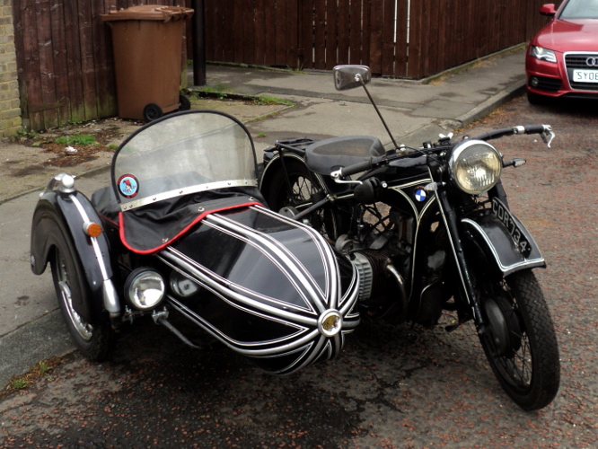
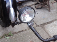
Last time out on the BMW R12 I ran into problems.

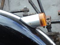
What happened was that she was blowing oil out from in front of the magneto and the entire left side of the motor unit was dripping with oil. It got onto the HT lead on that side as well and so was giving an intermittent misfire on that side, she’d run happily along the straight and level but show her a hill and the misfire appeared!.

Of course when the job was thought out and planned there were other items called for as well as those on the “Wish List” of items marked up as “I’ll get those next time I’m ordering something” so I wound up with a bill of around £100!, fortunately a couple of “extra” items were “Not currently available, Please re-order” which cut the bill almost by half and began a new “Wish List”.

When I had a closer look I could see it was blowing from the outside of the seal carrier plate so a new cork gasket seemed called for.

Once the bits arrived it was down to work.

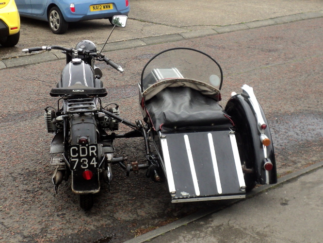
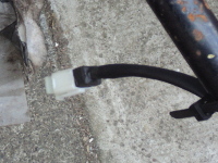
First thing was to get the sidecar off! Fortunately it’s mounted using Steib type DIN Standard fittings and the electrics are through a plug and socket connection so that was not a difficult or prolonged job, just a bit awkward when working on your own.

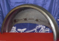
Then it was a case of clear the decks for action!. The tank had to come off to get easy access to the top of the engine unit, not an essential but it makes life SO much easier it’s worth the hassle.

But to remove the tank the seat has to come of first, and that bolt at the saddle nose is masked by the nose of the saddle and so is fiddly to undo and get out.

Now comes the not so obvious!. To replace the gasket I have to remove the magneto, which means it will have to be re-timed and on an R12 there are two ways to do this.

One way is to remove a cylinder head and set the timing 12mm BTDC on No. 1 cylinder. This means sacrificing an expensive head gasket. Not only that but on an R12 the head nuts are in between the cylinder finning, are awkward to reach and only accessible with an open-end spanner.

However there is the option of timing off the flywheel.

Some, but not all, machines have their flywheels marked for TDC and full advance. These marks are on the rear face of the flywheel and to access them means removing the gearbox, which means splitting the drive shaft.

My flywheel is so marked and I decided to go this route.

So, let’s get the gearbox off, Easy there’s only the two bolts through the clutch bell housing at 3 and 9-o-clock! If Only!

First is to get the shaft off, slack off the backlash to access the spring clip behind the drive flange, “persuade” it out of its groove (easier said than done!) then telescope and remove the shaft after removing the two nuts at the bevel box.

Next is to undo the two bell housing bolts, plus the one hidden under the engine at the 6-o-clock position!, I’ve seen a pair of crankcases that had been broken through forgetting this one!.

The gearbox still won’t come out yet because the long rear engine bolt goes through its housing!, so that has to come out and we’re not done yet! There are a pair of studs facing downwards in the bell housing itself at just below the 3 and 9-o-clock positions that allow the housing to clamp onto the gearbox and that need to be loosened as well before the gearbox will come out, promptly followed by an expletive as I find I’d forgotten that I’d put an earth lead onto one of the casing stud nuts!.

That’s the decks cleared for action, and it’s taken longer to do than the repair does.

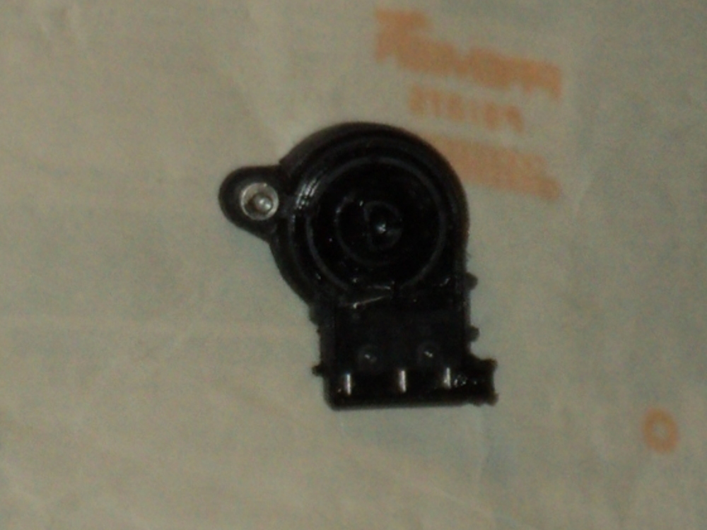
At the top front of the engine is a small cover held by two bolts, remove this and you have access to the magneto sprocket.

Book method now is to split the timing chain, undo the magneto securing strap and slide the magneto out, however it is also possible to tilt the magneto and gain just enough play in the chain to slip it over the sprocket and so remove the magneto without having to remove either the split link, or the sprocket securing nut and washer, with the attendant risk of dropping parts into the engine!.

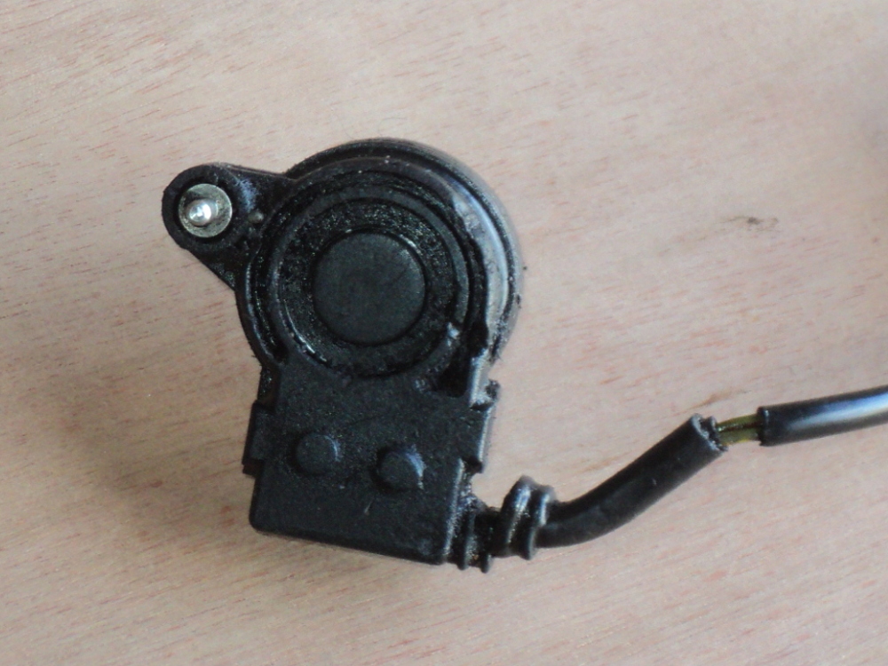
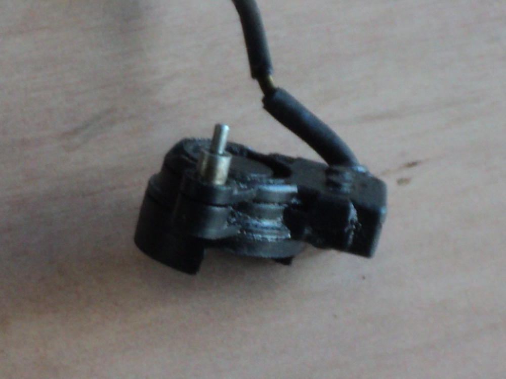
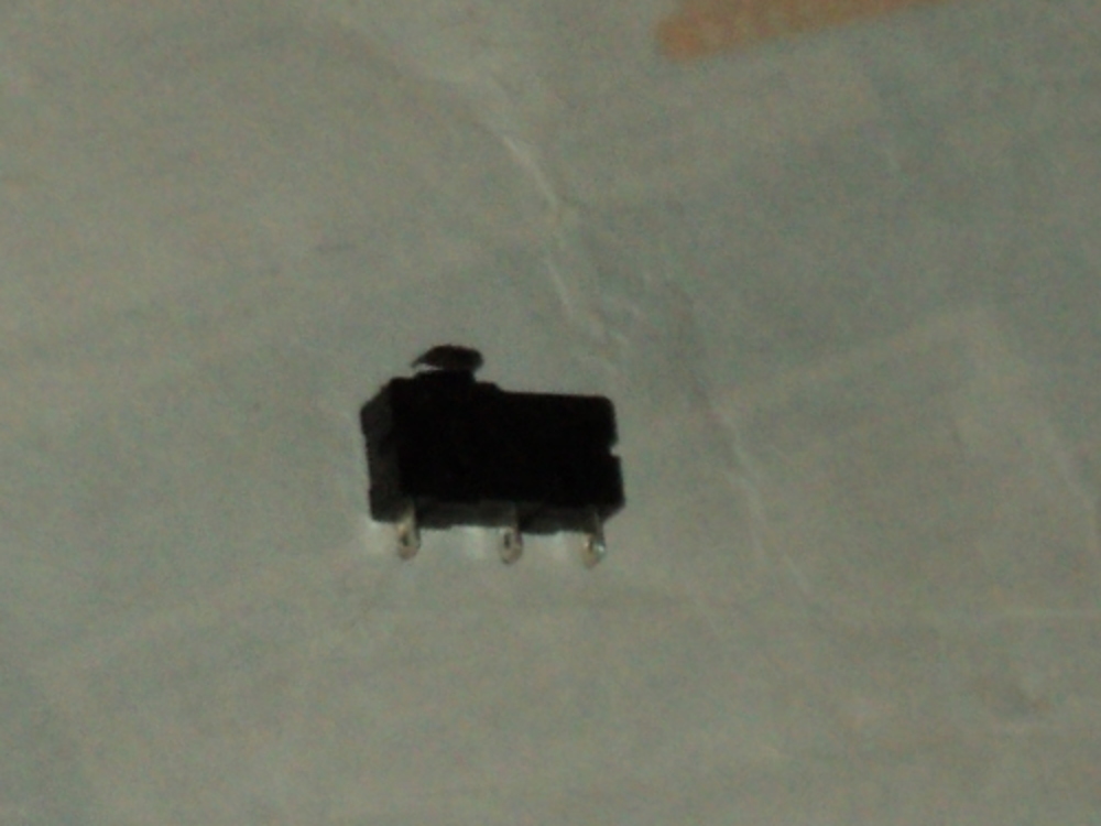
Once the magneto was off the problem became obvious, the cork sealing washer was compressed to the point of having no “give” and it was hard enough to strike a match on! No wonder it wasn’t sealing!.

Not only that, but there is a coil spring goes between the magneto and the seal housing to compress this cork gasket against the engine casing and this was “tired” to say the least! Fortunately I’d put a replacement for this spring on the list!

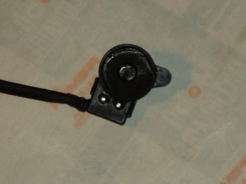
So now all that had to be done was to remove the magneto sprocket, replace the coil spring, refit the sprocket (leaving it loose), then grease up the new cork seal and refit the magneto.

Now came the fiddle! Retiming the ignition!

You set the timing on No.1 cylinder, the one on the right hand side so it’s turn the engine over till No.1 is on compression stroke and the timing advance marks are aligned, that’s step 1.

Step 2 is to set the magneto onto No.1 as well, this is with the rubbing heel of the points pointing towards the left and adjust the magneto so that with the ignition lever on full advance the points are JUST breaking, simplest way for this is a slip of cigarette paper (Rizla Blue are thinnest and best for the job) nipped between the points and then, when the points grip on it is JUST eased, to lightly nip up the magneto sprockets securing nut.

Now turn the engine over again a few times and then check that the points are still JUST breaking as the timing marks align and if they are then you can fully tighten the sprocket securing nut and replace the sprocket cover.

Now it’s just reverse the disassembly, offer up the gearbox with the usual hassle to get the clutch splines to match, and bolt the gearbox into place. Refit the shaft, slide the drive flange pins into the Hardy disc.

Now you just have to refit the spring clip into its groove, set the freeplay on the shaft to between a half and one millimeter and then all that’s left is to refit the tank and seat and we’re ready to roll.

After a test ride solo the sidecar has to go back on and here’s the beauty of the Steib, DIN Standard fittings, it is not necessary to re-align the sidecar the original alignments are still good, they have not been disturbed by the removal/replacement.

Chair Problems

A couple of posts ago I said I had a problem with the R80/2 sidecar outfit and I decided to get this sorted out before I started on the R12.

The problem I had was with the sidecar’s mudguard (fender).

On a Steib this is a big, Art Deco affair. Originally it would have been a pair of steel pressings spot-welded together but this was replaced with a fibre-glass (GRP if you prefer the term) replica about 40 years ago.

At the rear of the guard a chassis tube goes through it from side to side and the guard is held in place between a pair of conical mounts (there is a reinforcing cross tube goes here, between the two sides of the guard).

What has happened was that over the years the fibre-glass guard had gradually worn at the conical mounts until the inboard one pulled through. The guard then could move/bounce on the cross tube and by the time I got back home, I was some 150 miles from home when it went, the hole in the guard was not only oversize but oval. On further examination I found that the outboard mount was also “somewhat under par!.

Normally a repair on a fibre item is a simple matter, just clag on a bit more mat and resin! but here I needed to reform the seats for the conical mounts so I needed a former.

As I only needed to make up two mounts I just made up a temporary former using MDF board.

The maximum diameter of the conical mount was 50mm so I cut a round of inch thick MDF that size. The diameter of the cross tube is 32mm but as there needs to be a clearance on that I worked with 35mm as the minimum and I carved it down to a cone of those dimensions and 15mm high so I had a 35mm cylinder an inch high with a 15mm high conical base.

Next step was to make up a female piece to match this, as there was only space on the inside of the guard to take a 100mm square block this determined the outer dimension of the female mould.

When you are working with fibre-glass you normally have only a short “time window” to work in before the resin starts to gel and owing to the nature of my intended repair this was a problem.

However there is an alternative resin available, “Epoxy Resin” rather than the more usual “Polyester Resin” and this has a longer pot life, of around 6 hours plus rather than only 15 minutes and so I opted to use this.

Rather than just try to patch the guard I used the mould to make up a light support moulding for the main repair.

I took a 150mm square of MDF and drilled an 8mm hole in the centre, there was already a similar hole in the round male block so I fixed them together with a length of 8mm studding (allthread) and gave the resulting plug a good coating of mould parting compound, and I similarly dosed the female block.

Then I laid up the mould, using a layer of fine glass cloth and a single layer of chopped strand mat. I then put the female part over the centre piece and used the studding to force it against the lower part and left it overnight to cure.

When I extracted the “casting” from the mould I had what was to become the outer surface of the repair just needing trimming to size.

I then re-assembled the casting onto the mould plug, but this time sandwiched a sheet of polythene between them, the resin will not stick to this and it meant it would be easier to remove the plug.

A single layer of the chopped mat was now laid up onto the back of the casting and another onto the guard itself, being generous with the resin, the moulding put onto the prepared guard and the whole turned over to let me work on the inside of the guard.

The casting was adjusted for position to correct for the wear to the guard and the wear gap made good with mat and resin and then another two layers of mat and resin laid up on the inside of the guard.

I’d bored some 10mm holes through the guard so that the resin would bond through them to combine both sides of the repair together.

Once I had the inside laid up I put a sheet of polythene over it, put the female part of the mould over the plug and again squeezed the wet resin/glass layers together and again left it overnight.

Next day I removed the mould, a fairly easy job thanks to the polythene.

I then had to set to and repeat the whole process for the other side of the guard but once that was done all that was left to do was clean up the surface, fill the blebs with bondo, rub it down and get out the rattle cans to repaint.

It’s not a perfect job but you have to look to see it and as a new guard is around 250 quid plus carriage from Germany I’m willing to live with it for use on the road hack.

If I’d been willing to cut back with a sander on the outside of the guard after the repair it could probably have made to look as original but this is the main mount point for the guard and I’d rather a bit of strength over cosmetic perfection.

Parts Hunt

As I was needing parts to fix the R12 and there were a few other items on the “next time I order” list I sat down and drew up a shopping list.

Then it was a case of going “on ‘net” to source them. There are a number of places where you can get R12 parts on the continent so I checked them out to find that none of them had the full list!

I wound up ordering from Switzerland as they had almost the full list, all they did not have was a small gasket, one I can make myself if necessary. Parts were ordered one evening, two days later I received an e-mail saying they had been sent and the next day TNT were knocking on the door to deliver them!

Only snag was that the replacement seal carrier I wanted wasn’t available, “Please re-order later”!

So I turned to the only other place that listed that part, sent in an order and got an e-mail back that they did not have it in stock either!! Looks like there has been a run of R12s blowing their oil seals!.

Fortunately it is not a complex part so if the worst comes to the worst I’ll have to turn to and make one, only snag is it will mean having to trepan a groove in the carrier and that needs a fancy cutting tool, one I don’t have of course.

Blown Seal

After the run out to the Corbridge Show on the R12 the next outing was to the VMCC’s Scarborough Touring Week.

As this meant a week away under canvas I opted to take the old girl down there on a trailer behind the car. Reason for this was simply that I would have been unable to carry all the gear for a weeks camping for myself and the two dogs on the outfit.

On this event there is a road run each day and there is the social side each evening so it makes for an enjoyable week away.

Day One was the Friday with the run down the A19 towards York and then across to Scarborough. I chose this longer route because there are severe hill climbs with tight bends on both of the shorter routes, one being up Sutton Bank and that’s bad enough without a drag behind you!.

Anyway I got to the campsite in good time, offloaded the outfit and set up camp in time for the first evenings socialising.

The Saturday was a short run out, only some 60 miles around the area and everything seemed ok but when out on the Sunday problems arose.

The R12 has a separate Magneto/dynamo unit sitting on top of the engine. This necessitates a seal between the two and this blew. There is a carrier plate with a felt seal against the magneto end plate with a cork ring gasket sealing the plate to the engine housing and this is what blew, covering the left side of the motor in oil.

The oil got onto the plug lead and gave the spark on that side a pathway to track to ground and short out the plug.

Just to be awkward it would only track when the motor was under load, as when on a steepish climb, but when light loaded she ran OK! Typical!!.

I limped back to the main road on about one and a half cylinders and once on the main road it was a level run back to the camp-site so, of course she ran sweet as you like under the light load.

Monday was a run out to the aircraft museum at Elvington, near York, and rather than risk things I went over there with the two dogs in the car and had a good look round but I’d have preferred to be on the bike.

Tuesday was the “Extreme Hill Run”. I’ve done this run before using my R80/2 convert rig and it had tried the brakes on that lady so I had opted not to go on that run when I booked for the event.

This gave me a day “on site” when I could have a go at fixing the bike.

I tried various options at the “roadside get you home bodge” level but without success, it seemed the inner felt seal had gone and I was going to have to take the magneto unit off the bike to fix things.

This would have meant losing the magneto timing and this was not a job I wanted to undertake on a camp site, it’s not all that difficult but it is rather involved with an R12 outfit, meaning taking the sidecar off for access and then removing the gearbox to access the timing marks.

Wednesday I opted to stay on site again as the weather was rather inclement, i.e. it was p—ing down and while I could have gone in the car, I don’t see the pleasure in driving in rain any more than in riding in it!

Thursday dawned a nice day, but owing to other commitments at home I needed to back by Friday so it was a case of see the Thursday run out off, then pack up and drive home.

So, to fix the R12 I’ll need to get new seals and some other bits for her. These will have to be ordered up, probably from Germany, so it looks as if she’ll be off the road for the rest of the month, I’ve the R80/2 combo off the road with a repair to the sidecar so I’ve only a solo on the road at the moment.

Means I’m restricted in what I can do because of the two dogs, Looks like I’m just having to go to local events till I get an outfit back on the road.

First Run Out

Went out for a decent run on the R12 combo on Sunday, around 70 miles all told.

The sidecar chassis I’m using on her is the same one I took off her some 5 years ago when I started working on the Panther and needed the space in the garage.

When I put it back on I just bolted everything up “as was”, assuming the fittings had not been moved so, although Steib fittings are reputed to be good for this trick, I was a bit apprehensive first time out.

I’d taken her out first for a couple of miles to make sure there was nothing drastically wrong but this was to be the first real test of things.

So it was a case of load up, dogs in the sidecar, fire the bike up and away we go!.

All outfits tend to flutter their bars as you pull away, once you are used to driving an outfit you only notice this if it is excessive.

Use of a steering damper limits this but where your damper is the old-fashioned friction type it can stiffen up the steering generally.

I had my damper set at 3 clicks from off (one click gives JUST enough rub to keep the damper plates clear of rust when running as a solo) and did not notice any flutter worth commenting on so that was a good sign to start with.

Next was how stable the steering was. The R12 has a hand operated gear-change so you need to remove your right hand from the bars to change gear. If there’s any instability in the steering this is where it will show up and it didn’t, no wobble detected.

Now an outfit is a peculiar vehicle, it is a twin-track machine but is driven and braked on one track only. This means that, when the outfit is properly set up, on acceleration the bike tends to pull towards the sidecar and on braking the sidecar tends to pull towards the bike so that when on the open road much of your steering is done with your throttle. Much of the “Black Art” of sidecar riding is in getting to know how to use this.

If the set-up is incorrect then the outfit will tend to always pull to one side or the other. So, how was the R12?.

Answer is “Just about right!”. She steered nicely on the throttle and also ran straight when on a steady gas, it only needing one finger on the bars to hold her straight, always a good rule of thumb!.

After some 20 miles I took stock a bit, the R12 is lower built than the Panther, this results in the bars being lower than I’m used to with the Pussy and a feeling that I’d prefer them to come about a inch and a half further back and the same higher. I don’t remember this feeling when I was riding her before so it’s just going to be use.

The R12 has footboards whereas the Pussy has footrests, in theory there is greater choice of position on the R12, but it’s a boxer twin, you’ve a cylinder complete with carburetter in front of your foot so in fact there’s very little difference.

Another difference is that the R12 has telescopic forks in comparison to the Webb girder fork on the Puss.

Telescopic forks are at a disadvantage for sidecar work compared with either a good girder fork or a link fork, they have an inherent flexibility which does not affect handling as a solo machine but does affect a sidecar outfit, however those on the R12 have only a limited range of movement available, and given the limited performamce of the old lady this is acceptable in this case.

How did she perform?. Well remember the old girl is 80 years old and what was considered good back then is slow now. I have a Sigma electronic speedo fitted to her which has been set up on a measured half-mile nearby. On a major road along the level I was comfortably holding an indicated 41 to 44 mph. On hills this was dropping back to around 38 to 39 mph.

I was seldom over about half-throttle so there was power in hand, and one thing you rapidly learn with an outfit is to always have that “bit in reserve”.

Performance is comparable to that of the Pussy on chair, a difference being however that while the R12 is pulling sidecar gearing the Pussy was left to pull her normal solo gearing.

This means that under ideal conditions the Pussy will be faster on sidecar, she will tend to “bog down” more, requiring more frequent use of the gearbox and dependance on the intermediate ratios.

Conclusions are that I’ll soon get used to the R12 outfit again, that what is said about Steib fittings not loosing their alignment when the sidecar is taken off the bike is true, and that as I discovered when manhandling the two different chassis around off the bikes that the Steib chassis is considerably lighter then the Watsonian!.

Reason for this will be that the Steib is welded construction while the Watsonian is a hearth brazed fabrication with heavy forged lugs and straight tubes giving the Steib the same advantage the Featherbed Norton frame had over its rivals.

Meet The R12

Looking back on the last few posts I can see that I’ve been talking about the BMW R12 but there have been no pictures to show what that is, so this is her ladyship :-

This is showing the sidecar side view :-

Front Quarter view is :-

And the view most likely to be seen by other traffic (as they come up to overtake 🙂 )

And as they pass:-

A Further Update

I’ve had the R12 out a couple of times now and so it’s time to think of the sidecar. As I’ve said before this is a composite of a Steib S350 body on a Steib LS200 chassis

Steib LS 200 Chassis

Steib S350 Sidecar

First thing is lights!.

I can’t just swap the mudguard from the Panther’s chassis over, although this would be the simplest way, because the guard mounting systems are totally different, and anyway the LS 200 chassis is a Steib and so has the “art deco” flared guard rather than the old style half-circle guard.

Old Style Mudguard
Steib Sidecar Mudguard

The guard I have for it is a fibre-glass reproduction so the lamps on it need to be independently eatrthed, and then I’ve to fit indicators as well.

On a Steib the sidecar lights are built into the grab handle on the mudguard.

Steib Grab Handle

There is a tunnel cast into this handle that normally only carries a single wire forward to connect between the front and rear lights, power being fed into the handle by a hole through the guard at the rear mount.

This tunnel now carries the power leads for both the front light and the indicator as well as an earth lead, the leads to the indicator carrying on through the guard at the front mount of the grab handle.

For the indicators I’ve used a smaller version of the mounts I made for the Panther chassis, 2 inch diameter tube rather than 2½ inch and fitted with amber LED units sourced from the Internet.

New Indicator Units

I’ve changed to using LED bulbs in the grab handle as well and I’m using a stop/tail in the rear light.

Also, since the standard Steib rear light is rather small I’ve fitted an LED light into the rear reflector unit, so converting it into another rear light.

Steib Rear Reflector

This all means that now there is now a 4 wire loom leaving the mudguard to connect to the bike rather than the original single wire.

I’m also fitting a spotlight onto the chassis in front of the mudguard. This is also fitted with an LED bulb and is meant to act as both a DRL and as a running light.

Spotlight cum DRL

I’ve had to be a bit crafty here.

My R12 was built back in 1940 and her generator is of rather limited output, nominally of 6 Volts and all of 36 Watts!.

As standard on 6 volt electrics it would balance the lighting load of a solo machine and still have a little in hand to keep up the battery, but with a sidecar fitted there’s no leeway at all.

While I have converted the dynamo to give 12 volts output using a modern electronic regulator, which does help a lot, full lights on all the time are not really feasible, although the use of LED lights does help a bit.

So what I’ve done is to wire the spotlamp and the pilot bulb to work separately from the main lights, worked with a separate switch on the ‘bars, and I’ve fitted a 10 watt Halogen bulb in the pilot position as well.

The crafty is that there is also a feed from the sidecar running lights to the spotlight so that it will come on with the normal lights as well, I’m running with a right-hand sidecar in UK where the Rule of the Road is to drive on the left so I want a large front light on the sidecar side.

Problem is that doing this has power back-feeding both ways so with the lights switched off but the DRLs on the other lights come on as well so to counter this both feeds to the spotlight now go through diodes, as does the feed to the pilot light.

This means that I can now have two bright white lights showing to the front in daylight hours with only a small load on the generator but this extra load is not there when the main lights are on – so now, with the spotlight, there are 5 wires to connect between the bike and sidecar.

Traditionally this would be done using a nest of bullet connectors but I’ve opted for the neater way of using a 6-way “mini-connector”, as is used in a modern bike’s cable loom, with a feed for the other indicator in the 6th position.

This is because the R12 will comfortably be able to tow my lightweight box trailer and of course that means I need to feed all the trailers lights and indicators.

6-Way Connector

The trailer will make life easier when going on a camping event, my two dogs travelling in the sidecar and the gear in the trailer.

= = = = = = = = = = = = = = = == = = = = = = = = =

For any of you who want to tell me that LED lights are not legal to use on the roads I’ll point out that this bike was built in 1940 and so comes under the old regs.

These only ask for “A white light to the front and a red light to the rear” and do not ask for a kitemark or “E” numbers on the lights. After all people were still using acetylene gas lights on vehicles back then :^)}.

Update on the R12

Following from the last post the top coating repair on the front mudguard has been completed.

When I had a look at things the next day I was very happy as to the finish, the “Craftsman” paint I was trying out as a replacement for my old favourite “Tekaloid” came through with flying colours.

Only trouble was the contrast with the old paint, this had weathered over time so the new paint stood out like the proverbial on a barn door!.

So I broke out the “T-Cut” and gave the guard a good rub down and that did the trick, you no longer noticed the repair unless you looked closely, snag is I now have to do the rest of the bike to get it to match the front mudguard!.

The pressed-steel framed BMW’s, such as the R12, are quite heavily pinstriped so this repair has left a gap in the lining on the front guard that I’ll need to patch, so I now need to break out the lining brushes.

Lining is properly done free-hand and the difficult bit is getting a tight curve without smearing. My way round this is to mask out the line so that any smear goes onto the masking tape, problem is that with the BMW double line I’ll need to do one line and let it harden off before I can mask off to do the other.

I’ve also had the old girl out on the road for a run to see how things were.

I found that while she was willing to start and run, the start-up from cold was not as willing as it used to be and she was very reluctant to start from hot.

What I’ve done today is to treat her to a pair of new plugs, the old ones had been in for a long time now. I’ve also had the carburetters off and stripped and cleaned them, they have been standing for a couple of years and what fuel had been left in them had dried out and left a “varnish” of crud inside the passages and jets.

Fortunately she’s running on a pair Amal 276’s and these are an easy carb to strip down and clean.

I’ll need to synchronise the slides opening before I take her out again and while that’s a fiddly job it’s not that difficult.

I’ve also offered up the sidecar chassis to the bike. Before I actually fit it I’m wanting to rig a sidecar brake. I had a sidecar brake on the Panther outfit and found it useful, after all the bikes brakes are from the 1930’s and brake technology has come a fair way since then so every little helps.

The rear brake on the R12 is operated with a heel operated pedal on the right-hand side. What I’m doing is to mount another pedal onto the sidecar chassis with a lever coming straight across to the bike and level with the bike’s rear brake pedal, so that its pad lies alongside the bike’s one. This means that when I apply the bike’s brake I’ll also apply the sidecar brake as well, and by rocking my foot I can vary their relative pressures.

However I’ll also be able to apply either brake on its own to give differential braking which can be useful to assist in cornering.

Only thing now is that while I’ve the brake pedal set up I’ve still to arrange the cable fitment at the drum end of the system, as a “By The Way” the chassis I’m using is from an LS200 Steib. The wheel is from a Ural/Dneiper, a half width hub that looks in keeping with the R12 and the brake itself is an Enfield type from a rigid-framed Panther.

What’s Happening??


It’s been a while since I posted anything on this blog, too long! But there’s not been much happening with the bikes as they’ve been running well. However I’m feeling in need of a change now so–.

I took the sidecar off the big Panther a couple of days ago, not the easiest of jobs when working on your own, but do-able, the body is now up on a pair of trestles in the shed and the chassis is in the back yard.

The Panther now stands as a solo in the garage, but she’s not on her own as the old BMW has been brought out of storage and is standing beside her. They make a good pairing, the 600cc 1937 Panther M100 and the 750cc 1940 BMW R12.

Although the Panther has the smaller displacement engine of the two she is the more powerful at 26bhp to the BMW’s 20bhp, but the BMW is a twin cylinder side-valve with a heavy external flywheel so is possibly the better slogger of the two, still neither was intended as a sports bike.

Anyway the BMW is set up with a full set of Steib quick release sidecar fittings so once I have the chair set up for her I can drop it on and off in around five minutes work, Useful!!

Now, what does the BMW need doing to get her in commission again?

Well her battery is an AGM sealed unit and has survived her laying up, still showing about half-charged when I put it on the charger. She is magneto ignition and that’s sparking well but I’ll treat her to a new pair of plugs.

How about oils?, well oil is cheaper than metal so it’s new oil all round, and owing to her age it’s an old-fashioned non-detergent type oil. Equally I needed new drain and filler plug gaskets.

On a machine of this age these should be the hollow rolled-copper type rather than the solid aluminium ones BMW now supply. A quick rake round on ebay soon found a supplier of these in the neccessary 14mm and 18mm sizes.

Rather than run her up to hot on the old oil I let her drain out overnight and then it was just a case of fill the engine to between marks on the dip-stick and the gearbox and final drive until the oil reached the bottom of the filler hole threads.

Now came the acid test, she’d been stored with a dry tank so I put a half-gallon of fuel into the tank, no leaks visible! GOOD!!, turn on the tap (which way is “ON” and which is “RESERVE”??, I can’t remember!! ).

OK, the carbs had filled so a good tickle on each carb, crack open the throttle and turn over the engine several times to prime the cylinders, then it was just switch on the ignition and kick her over.

While she fired she didn’t pick up so a tad more throttle, try again and the old girl was running again! Tick-over balance is a bit off but I’ll need her warmed through to set that up so it will have to wait.

Now I know she’s a runner what else needs doing.

An immediate obvious is indicators!. Last time out she was hauling the chair.

I know it’s non-original but on modern roads an outfit NEEDS indicators and now you can use LED units without overloading the electrical system so she was fitted up with lights on one side, the others being on the chair. So it was get another pair of indicators and fit them.

I had to make up (and paint) a set of mounting brackets for them, run in the wiring and then tap it into the circuit to the sidecar indicators, a quick check and found they were working.

Next thing was cosmetics, the front mudguard needed some serious touch-up where the paint had been badly scarred and had started lifting while the old lady had been sitting in the storage unit.

Fortunately it can be redone while still on the bike as it would be serious hassle to remove it and then given a dose of “T-Cut” after about a fortnight’s curing followed by a polish job should see things OK.

As I’m writing this she’s standing in the garage with the first top coat on the guard giving it time to harden off before she’s put away for the night, another coat tomorrow should then see it ok.

I can’t really complain as both guards were in a bad state when I got the bike back at the beginning of the Eighties and they needed serious patching to be made usable, since then she has seen some serious mileage!

BMW R850R Side Stand Switch

On the “oilhead” model BMW’s there is an interlock switch so that you are unable to pull away with the side-stand in the down position, you cannot even start the engine when it’s in the down position.

This is done by having a switch that is operated by the sidestand, a BMW special incorporating a micro-switch.

On my R850R this switch had gone permanently open circuit, so I could neither start or run the bike.

On visiting my local BMW emporium for a replacement I found that it was “Not Currently Available”, while it is still a listed spare there were none available, not even in Germany, not only that but they’re grossly overpriced for what they are, according to the dealer the current price is just over £110 !!.

Fortunately it is a simple matter to bypass the switch, so I was not left with an inoperative bike but to do this I had to bypass a safety system, not the best of ideas!.

So, nothing ventured nothing gained, I removed the switch to have a look at it.

Interlock switch

The interlock switch

As expected it was not meant for servicing but when I had a good look I could see how it had been assembled.

There were a couple of moulded tabs and a steel locating pin so first step was the pin.

Switch peg

The metal locating pin half-way out

I gripped this pin with a pair of pliers and it came straight out with a twist and a pull. I then pried the tabs back a little and ran blade round in the joint  between the parts of the assembly.

It took a bit of fiddling what with having to pry and split at the same time but the two halves soon came apart.

Split housing

The opened housing

Now I could see how it worked, there was a plastic cam bearing onto a micro-switch.

In bits

The switch components

The micro-switch body was deeper than the standard one but since it had the wiring loom coming direct of it rather than having the more normal terminals this is probably why.

Anyway, because the standard switch is shorter it can easily be fitted into the available space and it can then be fixed in place.

So I now needed a suitable switch and the obvious place to try round here was the local branch of MAPLINS.

A look on their website confirmed that they had a range of micro-switches, all in the C.O.(Change Over) format, that is that rather than their being simply either N.O.(Normally Open) or N.C.(Normally Closed) their connections were switched from one state to the other.

This meant that I had no worry as to which was the correct conformation for the job, it was just a case of finding which one would fit best into the casing so it was off to the local branch.

Button switch

Plunger type micro-switch

Once there I soon found a snag, the switch plunger on the new switch did not touch the cam.

It turns out that the standard “offset” on a micro-switch plunger is 1.2mm and BMW in their ineffable wisdom have elected to use a non-standard switch.

Idea is presumably to force the purchase of their dedicated (and expensive) switch but however there is a way round this snag, there is an alternative switch has an operating lever.

Leverswitch

Basic lever type micro-switch

This lever that can readily be bent into a suitable shape using round-nosed pliers, so I got one of those switches at a price of £2:29, that’s just not quite 1/50th of the price of the BMW part.

lever modified

The lever bent to shape

Once I had the lever bent into the requisite shape I found that the plastic housing round the cam was fouling on the base of the lever and this was preventing the new switch from going fully “home” into position in the housing, but a little careful easing with a router bit in the Dremel soon got round this.

switch in place

Lever switch installed in housing

Now the switch had to be fixed in position. The original had located with pegs on its sides that located into recesses in the housing but the new switch body had a pair of mounting holes rather and these were just under 3 mm in diameter.

These holes however lined up nicely with the recesses in the housing so it was just a case of opening these through to take the appropriate countersunk head bolts.

Assembled unit

Finished job with screws in place

I’ve committed the heresy here of using the old 6BA size for this, simply because I had some in stock along with having the appropriate tap, rather than having to buy in metric machine screws and taps.

All that was left to do was connect the wires to the switch and close up the housing, test the whole assembly and then, once it was found to be working, refit it to the bike.

Job Done!