Category Archives: Panther

Panther motorcycle restoration

In Drag

When I first took the old lady out for a ride I found that her clutch was dragging badly.

When you are setting the clutch up, the individual clutch spring tensions are adjusted until you get an even “lift” when the handlebar lever is operated and when I initially set this one up I had problems getting the spring plate to lift evenly.

As the springs are all identical then the amount their adjuster are screwed in by should be fairly close to each other and these were not.

This indicates that the springs are “tired” and should be replaced so I got a set sent up from the Owners Club spares scheme.

To fit them requires a bit of dismantling, on late models there is a separate dome cover over the clutch and to work on the clutch you just need to remove that but life is not so easy on the pre-war machines.

With these you need to remove the complete outer primary chaincase, to remove that you need to remove the footrest and to remove that the exhaust syatem on that side has to come off!.

Primary Drive

Primary Drive

Once the primary case is removed you have access to the clutch and the springs.

There are five springs in the Panther clutch, each fitting into a spring cup in the clutch face-plate and secured in place by a sleeve nut with a screwdriver slot in it.

Clutch Exposed

Clutch Exposed

I unscrewed one of these sleeve nuts, removed the spring and compared it against one of the new springs and found the old spring was noticeably shorter, it must have “settled” a bit over the years.

Springs compared

New and Old Springs Compared

Then it was merely a case of putting the new spring in the spring cup and fitting the sleeve nut, sounds easy but it’s not due to the spring pressure.

Since the adjusters are a sleeve nut rather than a screw you need a special screwdriver with a gap in the blade to allow for the stud that the sleeve nut screws onto.

spring tool

Spring Adjuster Tool

This shows the tool I used, it’s made from a bit of 1/2inch hexagon bar with a 1/4inch hole drilled down the middle and the end ground into a screwdriver blade.

By fitting it into a socket on a “T”-bar I can put an even pressure on the springs and turn the sleeve nut to engage it with the threads on the stud.

The springs were replaced one at a time and then all were tightened down till they were solidly coil bound.

They were then each turned back by four complete turns to give the base setting.

The clutch was then operated several times to settle the springs in their positions and then operated while watching the face-plate lifting.

The springs were then individually adjusted until the plate was lifting straight and even.

As on this occasion there was no need to replace any of the clutch plates there was no need to reset the free play in the clutch cable but if I had renewed the friction plates this adjustment would have been needed.

The effect of new, thicker, plates is to increase the free play in the system and there are two ways to adjust this out.

The obvious way is using the cable adjuster where the cable enters the gearbox but this is limited and there is also another adjustment on the internal lever inside the gearbox.

This adjuster is to be found under the small cover seen here by the kick-start lever.

 Adjuster Cap

Fulcrum Adjuster Cap

This cover is held in place by two screws, once these are removed the cover can be lifted off revealing an adjuster nut which alters the fulcrum point of the internal lever.

Adjuster Nut

Fulcrum Adjuster Nut

Since the underside of the cover is recessed to fit the adjuster nut, the simplest way to adjust this nut is using the cover to turn it.

However the cover must be screwed firmly in place before you can operate the clutch as it is the anchor point for the fulcrum.

Pedalling about

The last of the foot controls needing “adjustment” was the brake pedal and this was also the most awkward one to do.

When I got the bike it was in this shape and not knowing any better, I assumed this to be correct:-

Brake pedal old

Brake pedal “As Was”

Bent Lever

Bent Lever


As you can see the way the cables attach to it means there is a lot of “lost” motion of the pedal before there is effective movement of the cables.

Yes “Cables”, this old lady came with her front and rear brakes coupled together as standard.

At the pedal the top cable works the front brake, the bottom one the rear, all this back in the 1930’s, about 50 years before the Japanese manufacturers “invented” the system :^).

On closer examination it was found that the pedal lever was twisted at the point where it curved down and the toe-piece was bent in towards the bike.

In order to bend a steel forging like this it is necessary to get it up to high temperature, when it can be bent like warm toffee, so a gas torch was brought to bear on the job.

First thing to do was take out the twist and removing this almost completely eliminated the bend.

This had two other, connected,  effects though, first was that it very effectively removed the paint from the lever and the other that once the paint was removed an earlier repair was revealed.

At some time before I  got her the old girl has been dropped and this must have been the cause of the bent lever, however when being dropped the toe-piece of the pedal had also been snapped off.

This had been repaired by simply butting the two broken ends together and then brazing the joint up, so effectively the leverage to trhe rear brake was being taken by some brass brazing rod, Not an Ideal Situation!!

If the joint had been splinted as well then it would have been an adequate repair but not as it was.

To make a better repair the break was cleaned up, dressed and grooved.

The whole pedal was then set up on blocks so the toe-piece was correctly aligned and the parts “TIG-welded” together, this way the repair will be as strong as the original pedal was.

Once the lever had cooled down it was then dressed back and then given a coat of etching primer before having the imperfections made good with filler.

A few coats of primer/filler were then sprayed on and allowed to dry overnight.

Once this had been rubbed down smooth and level the black topcoats were added, followed by a couple of coats of clear lacquer and this was the result:-

Repaired Pedal

Repaired Pedal

Repaired Pedal2

Repaired Pedal

Now the cable is making a 90 degree angle with the lever arm when at full stroke, which is what is required, not only that but the “lost motion” has been eliminated, giving a better “feel” to use of the rear brake.

Kickstart Repair

The repair to the kickstart was a bit more involved. On this there is a foot-piece which pivots on a boss formed on the main shaft of the pedal.

The problem was caused by the “eye” of the footpiece being worn. This had allowed it to slide against the limit stops so these were worn as well but fortunately there was very little wear on the boss the footpiece pivoted on so it was decided not to worry about the boss.

The “eye” first had to be bored out until it was a true bore, simplest way here would have been to clamp it on the table of a vertical mill and clean it out with a milling cutter.

Not having a mill I clamped it in a 4-jaw chuck on the lathe. To get it centred I cheated a bit by clamping a bit of 1/2inch bar stock in the tailstock, putting it through the “eye” and clamping the footpiece in the chuck using that as a guide, being a trusting soul though it was checked before commencing work.

In Lathe

Centring the pedal in the 4-jaw, The mandrel is purely to aid in this.

Once the footpiece was clamped up it was soon bored out true and enough oversize to take a thinwall bush.

To fit the bush it was frozen with an aerosol blaster and dropped into the “eye”.

As intended it proved too tight to fit onto the boss and so was reamed to a slightly stiff fit and then the boss burnished to ease the fit.

Next job was to make good the limit stops which had worn angled.

Footpiece

Foot-piece opened out and bushed.
The limit stop has been welded up but not yet reshaped

These were filed back to square. This meant however that in the “at use” position the footpiece was angled backwards so the stop on the pedal was built up with weld and then shaped using a Dremel grinder so that it stopped just before the right angle position and the stops were making full contact.

Doing this means that as pressure is put on the footpiece your foot will tend to slide in towards the pedal shaft rather than out and off the end of the pedal, something that is not to be recommended when using any kickstart, never mind one on a 600cc, long-stroke, single.

The foot-piece was assembled onto it’s shaft but when the end nut was fitted in place there was more vertical play than I liked, the nut was bottoming out on the end of the boss before it reached the top of the footpiece.

This was got round by making up a recessed washer to go between the nut and the end of the boss that would take up this play and once this was fitted the kickstart was as good as new.

Gear Reset

After re-routing the clutch cable, next of the problems to be fixed was the gear-pedal.

This is an alloy lever and a characteristic of this material is that it will age harden, that is as it ages it becomes harder and less flexible so if you try to bend it “as is” it will almost certainly break.

If it is heat treated, or “annealed” first then it can be bent, but you need to be careful since it also “work hardens”, this means that the bend should be put in in one smooth pull.

The lever had to be heated to the correct temperature, the easy way to determine this was to smear some soap onto the lever and then gently heat it until the soap blackened.

The spline end of the lever was then clamped in a vice and steady pressure put on the other end to move it across by the required amount.

lever reset

Re-setting the Gear Lever Alignment

This meant that the toe-piece was now at the wrong angle but as the whole lever had been annealed then this could also pressed  back until its angle was correct.

Toe reset

Re-setting the Toe Piece

When the pedal was put back onto the bike it now cleared the exhaust sufficiently that the pedal could be moved far enough round on its splines for me to be able to change gear easily.


Teething Problems.

Having fixed the problem of the slipped timing I’ve had the old girl out two or three times now and have found a few of what may be called “teething problems”.

Number one was that the clutch action was very heavy.

To fix this I had a close look at the control cable run and have re-routed it. This means that the bends in it are gentler and the action, though still heavy, is now much improved although the look of the run is not as “neat and tidy” as it was.

The cable itself is not a “nylon lined” type and a further step will be to look to upgrading to the use of this type of cable.

The clutch was also found to be dragging.

When setting it up I had problems getting an even lift of the back-plate. Since this is done by adjusting the compression of the individual springs the clutch pressure springs are suspect because they are not evenly compressed.

While “tired” springs would seem to be more productive of a slipping clutch, in getting the plate to  lift evenly their adjustment can limit the amount of lift available, thus causing the drag, so a new set are going on order and the clutch will then be set up from scratch.

Other problems were found with the foot controls.

One of these is that the gear pedal is set as far down on its splines as possible, any further and it will foul on the exhaust when changing down. Even so, due to the fact that I am a long-legged beggar the angle my foot is at on the rest means I cannot bend my ankle far enough to change gear without taking my foot off  the rest.

By bending the lever outward enough to clear the exhaust I will be able to move it round by another spline on its shaft and so solve this problem.

The lever is an alloy casting and it will need to be heat treated first, then bent while hot, not only that but the angle of the toe-piece will also need to be adjusted afterwards.

Then we have the kickstart lever.

This has a folding foot-piece which pivots on a boss formed on the end of the vertical lever.

The “eye” in the foot-piece is worn oval and the boss is worn barrel-shaped so the boss will need to be built up and reshaped while the foot-piece “eye” needs to be bushed to match the new boss

Not only that but the “stops” on both the foot-piece and the lever need building up and re-shaped so that the foot-piece will stop at 90 degrees to the lever, rather than as it is where it stops some 20 degrees past this and your foot tends to slip off the foot-piece half-way down the stroke. This is not ideal when trying to start a big Panther!.

The last foot control is the rear brake.

At some time before I got her the lever has been broken and welded up. When this was done the lever was also re-shaped, bringing the toe-piece further down when in the “at rest” position.

The result of this is that the toe-pad is contacting the exhaust before it’s rear brake actuating arm reaches full stroke.

Seen from the side the lever at present is crescent shaped where in fact it should be straight so this lever is going to have to be brought back to its original form.

None of these can be said to be a major problem but all will need to be remedied before any serious riding can be undertaken.

First Time Out

As it was reasonable weatherwise today I decided to bite the bullet and try the old girl on the road.

So I kitted myself up and brought her out of the garage.

Expecting a bit of effort in starting her I put my helmet and gloves on the ground, turned on the juice, full choke, about 1/3 advance and wound her over twice to prime.

Then it was find compression and ease her over it using the valve lifter, give a “long swinging kick” and what do you know! — she starts and runs first kick!.

So I set her down to half-choke and her let warm up until she’d tick over reliably then it was put on my helmet and gloves and take her off the stand.

I went to change into first gear and found the first snag, the gear pedal is too high!.

So it was reach over and hook it into gear with the back of my heel, I can’t set the pedal further down on its splines as it will foul on the exhaust so some “adjustment” to the lever will be required.

G-R-A-U-N-C-H,  The clutch was dragging!, well I think best thing for that will be new springs and re-set up with those, it was a fiddle getting an even lift with the ones I used.

Still I was in gear now so it was ease the clutch and pull away.

I went to change into second and had to take my foot off the rest to work the pedal, definitely looks like I’ll have to “adjust” the lever so it will clear the pipe!

Okay, next thing I was coming to a “T” junction so it was gear down and brake, H’mm brakes weren’t as good as they seemed on static test, maybe they just need to bed in —  or perhaps a reline is in their immediate future — not only that but I can see the coupled brakes will take getting used to.

Junction was clear so it was just roll through the turn, retard the ignition a little and throttle up, engine note deepened and she pulled strongly away as I eased on the ignition advance, I’d forgotten the feel of the torque on a big Pussy!.

I pulled into the petrol station a mile down the road and put a gallon of juice in.

The bike had been running so well I decided I could put up with the gear-change for now and would put a few more miles under her belt.

So it was going round roundabouts, swinging through bends and enjoying using the sheer slogging power to pull me round them, she responded well to use of the advance lever and on the hills just “settled into the harness” and pulled on up them.

I can recall it being said in a magazine somewhere, somewhen, that a Panther might only have 26 horsepower, but these were real horses, ones with shaggy legs! (was it Titch Allen said it?, sounds like one of his comments).

I was really enjoying things until, about 12 miles out from home she lost power and I had to stop.

She turned over easily with plenty of compression so the mechanicals seemed OK. Plenty of fuel in the carb, was it electrical?.

A bit of checking of the magneto and it turned out that the magneto coupling had slipped on its taper!, if you prefer it, the timing had slipped.

Strangely enough, the first time I was out on her some thirty odd years ago the same thing happened but that was with a Lucas N1 mag and not the BTH unit she’s wearing now.

Fortunately I was within a mile of a friends house so we soon got her up to his place, he ran me home and I came back with the van to pick her up and spend a couple of hours chewing the fat with him.

Bit of a downer finish to the ride out but given about an hours work tomorrow and I’ll have her running again, I’ll lap the tapers to make sure of a good fit and clean them with a solvent cleaner to make sure the cones are absolutely clean.

It was a real pleasure to ride her again after all the years, the way she just digs in and pulls when you ask her to accelerate, the feel of riding the torque curve of the motor rather than the power curve, the lazy feel of a big, slow revving, under-square single.

I can see riding this old lady being addictive! While she’ll not be a motorway bike but she will revel in the twisties of the older road system, but after all those are the roads she was built for.

There’s Life, Jim!.

Well the last stages are to fit the final drive chain-guard and to set up the dynamo.

As there was no chain guard with the bike when I got her I had to see what I could do.

Rear Chainguard

Panther Rear Chain-guard

On checking photo’s of other machines of this period I found that it was a bit of an odd ball in that it had a flare up at the rear end. Needless to say this part is one that is not listed in the Panther Club’s spares scheme so I would have to make do.

As it happens the old lady has a stable-mate, a late model Velocette, and on checking my parts cache for this I found a damaged rear chain guard, it having the rear end almost completely broken away.

On offering it up to the Panther it was immediately obvious that no way would the Velo mountings line up with the Panther’s, not only that but the guard was too long.

Measuring it up soon showed that if I cut the guard at the front mounting bracket it would be the correct length so that got rid of one problem completely and half of the other.

The rear Velo mount is a bracket welded to the guard that picks up onto a mount on the Velo’s rear swing arm, but the Panther has a rigid frame, the mounting lug for the rear of the chain-guard is on the mudguard-stay and would not match the Velo bracket.

But the Panther mount matched onto the guard itself so I decided to just remove the bracket and get a nut welded onto the cover at the correct point, using a set bolt to retain it.

Another snag was where the rear frame stay came across the guard as it needed a recess formed in it to give clearance but a little careful work with a cross-pein hammer soon cleared that problem up.

So after getting things sorted out I went over to have a word with Bob at Specialist Services again.

He did a beautiful job of welding up the cracked rear end of the guard, not only that but he buffed it back smooth again, and then fixed the nut onto the side.

Once I had it back home it was out with the filler to make good the surface and then paint the guard before it was fitted to the bike.

Velo guard

The Modified Velo Chain-Guard

This left me with the dynamo to do.

While it checked out electrically sound, the drive end bearing was a bit rough so it was a case of getting replacement bearings and fitting them, an easy job.

With the new bearings fitted the drive sprocket was put onto its taper on the armature and tightened  down.

The dynamo was then slid into its housing and the drive chain slipped into place on the sprockets.

Dynamo Chain

Aligning the Dynamo Chain

The dynamo was adjusted side to side until the sprockets were in alignment and the chain free play set.

Before connecting the dynamo to the new, solid state, regulator its output needed checking, and to do this it has to be running at normal speed so preparations for this were made.

There are two outputs from the dynamo, one labelled “F” and the other “D” plus a ground connection made through its casing.

The “F” and “D” outputs were connected together and these joined outputs connected to a headlamp bulb, the other side of the bulb being connected to ground.

Now came the acid test, I had to get the motor running for the first time in some thirty years.

So a half gallon of fuel was put into the tank, the tap set to “Reserve” and turned on.

After giving the carburetter time to fill the choke was set to full on, ignition lever to half-way, valve lifter raised and the motor gently turned over several times to prime it.

Ease over compression and give the traditional “long swinging kick”  – – Nothing.

Tried again, once again nothing.

So I tickled the float for a couple of seconds, primed her again and then the next effort to start her was met with a vicious kick back – – –  AHH, Signs of life! That’s more like it!

Set the advance back a bit more and try again and she was running.

So set the choke to half open, add a bit of advance and then just listen to the noises!

No undue clatters, tappets quiet, all seems as it should be so I shut the throttle and she was ticking over, rather fast but doing it and by now I had the choke off completely so I grabbed a screwdriver and set the throttle stop down a bit then played with it and the pilot air adjuster to get a reasonable tick over, I’ll have to do it properly once I have her thoroughly warmed up but this’ll give a good start point.

So with a feeling of satisfaction of a job well done I shut her down, – – – – and then realised I’d forgotten to check the dynamo output! Typical!.

So I had to fire her up again, only to find that the test light was staying out, the dynamo apparently was not charging so she was shut down again.

Before going any further I checked the bulb was ok using the bikes battery.

As a sidenote here, these old ladies used the old type black, rubber-cased batteries, which were mounted visibly, Panther mounted theirs on top of the rear engine plates, above the gearbox.

To keep the correct period look you can take an old battery of this type, gut it of the old plates and separators to give an empty box and then fit a modern battery inside which is what I have done, in fact to be honest I’m using the one I did previously for the Velo.

There are specialist dealers, such as Burlen , who can supply you with a casing ready modified and already containing a suitable battery.

Anyway, as the dynamo had been standing for so many years it seemed probable that it had lost the residual magnetism it needs to start it charging and that it just needed “flashing”.

To do this I took a lead from the battery positive side having first connected the battery negative to ground.

I fired the bike up again, brought the revs up to a very fast tick over and then just tapped the battery positive lead to the joined dynamo leads. NOTE the connection was literally just made for a fraction of a second and then immediately broken, it was not a permanent connection.

The idea is that the quick power pulse produces a magnetic field in the field coil of the dynamo BUT as the coil only has a low resistance and it is effectively a short-circuit on the battery you cannot leave the connection made.

Once that field is created with the dynamo running, it becomes self re-inforcing and the battery current is not needed, it can in fact cause severe damage if left connected for too long.

This did the trick and with the dynamo charging it was now just a case of connecting it to the regulator, fitting the dynamo chain cover and that was things set for the first ride.

Here’s a look at the old girl in her new clothes ready to go out on the town.

Right hand side

Timing Side View

Left Hand Side

Drive Side View

The Gasworks

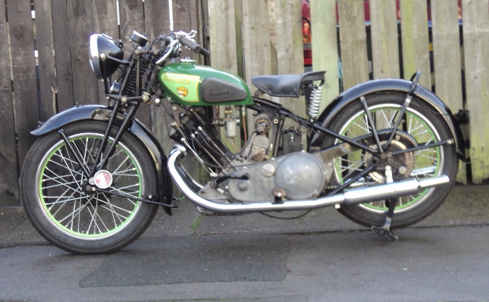
Next is to strip and clean the carburetter

No, that’s not a mis-spelling, the bike is fitted with an AMAL instrument and they have always used this spelling for their product so if it’s made by AMAL it’s a carburettEr and if it’s from an other manufacturer it’s a carburettOr.

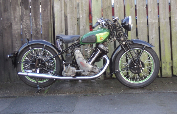
Pre 1955 AMAL supplied their 276 and 289 series, these had a separate mixing chamber and float chamber and it’s this type that’s fitted to my Panther.

Strictly speaking I should be using an instrument from the even older 76 and 89 series as the 276 and 289 types came into use in 1940 when there was a design change in the pilot air inlet system but my bike has been fitted with this later type at some time in it’s life.

Amal carb

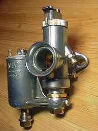
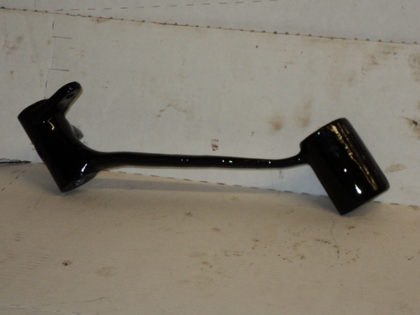
A complete Amal 276 carburetter

First step is to remove the float chamber.

This is attached to the main body by the nut at the base of that chamber, undo that and the fuel chamber comes away in your hand, exposing the main and needle jets, and can be put to one side for later.

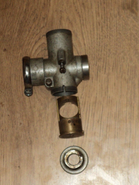
The main body or “mixing chamber” is basically two tubes in a cross, the horizontal tube being the main airway and the vertical one contains a brass jet block held in place by a ring nut screwed onto its base and it also contains the throttle and choke control slides.
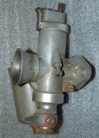
Amal2

Mixing Chamber

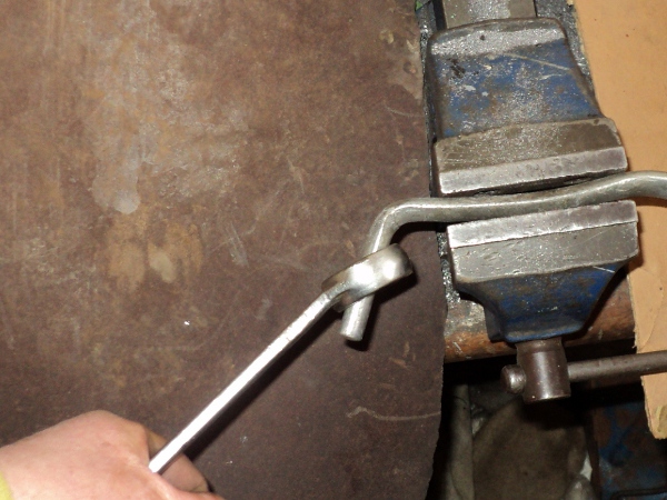
This chamber comes apart by first unscrewing the knurled ring nut at the top of the vertical, (on mine the thread in this nut is worn and it has to be replaced).

You can now withdraw the choke and air slides from inside the body.

There is also a large ring nut at the bottom of the body, with a hexagon to take a spanner/wrench and removing this gives access to remove the jet block (but remove the main and needle jets first).

Amal3

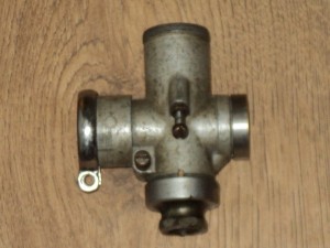
Jet block is retained by this ring-nut

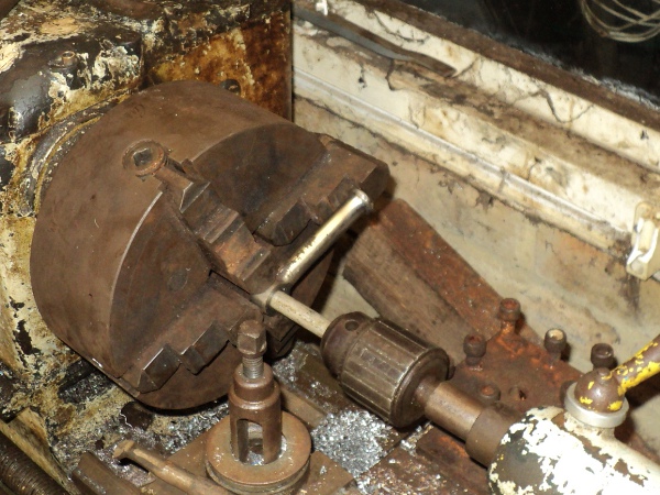
This ring nut is the same thread form and diameter as the knurled ring nut at the top and so I used this to check that the threads at  the top of the body were sound.

The jet block is a light press-in fit into the zinc/alloy main body and will readily push out. Notice that there is a special composition washer goes between the base of the jet block and the nut and that the correct gasket MUST be fitted (some cheap, pattern, gasket sets supply a paper gasket for this that is too thin).

All that’s left in the main body are the pilot air screw and the slide stop screw so these were removed and the whole assembly of parts put into an ultra-sonic cleaning bath.

After a session in this bath the passages in both the jet block and the main body were blasted through with an aerosol carburettor cleaner and then the whole lot were given another session in the ultra-sonic bath before they were allowed to dry off.

Come re-assembly and first step is to fit the jet block into the main body, as this is a light press fit and I didn’t want to use force here the body was heated up in boiling water and then the jet block fitted.

You need a bit of attention to detail here as it is possible to put the jet block in in two ways and only one of them is right since when it’s 180 degrees out of phase the passageways in the body and the jet block don’t line up with each other.

Amal10

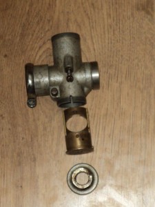
Mixing chamber, jet block and ring nut

With the jet block fully home in the body you next fit a new composition washer and then the bottom cap nut, it’s a good idea to fit the needle and main jets now as well, you can fit the fuel chamber’s banjo bolt loosely here just to keep any muck out of the jets.

The throttle slide has the needle position checked that it’s in the correct notch and is then slid into place and its easy movement checked, you can also check for wear in the slide and body by trying to move it back and forwards in the body. If needs be it is possible to have the top of the body bore out to true again and the slide sleeved to fit the new body, if the whole length of the body is bored out then you’ll need to get the base of the jet block sleeved as well so make sure whoever does the work for you knows what he is doing.

Now is a good time to fit the slide stop screw since you can keep a finger on top of the slide while you fit it and so find the exact point at which the slide is being raised off the the mixing chamber’s floor.

Once it starts to lift give it one full turn more to give a “set up” position to the slide.

Amal5

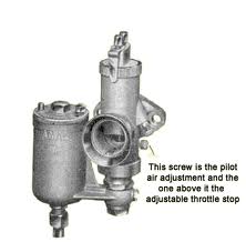
Throttle stop and mixture screws

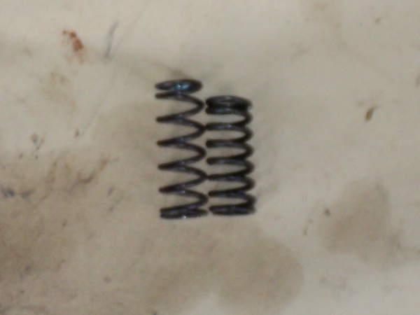
The choke slide is next dropped into place along with it’s guide tube and spring,

Then the throttle slide spring and the mixing chamber top is fitted and secured with the knurled ring nut.

Only thing left to refit is the pilot air screw and this is screwed in until it bottoms and then turned back one and a half turns to the “set up”position.

While doing all this the float chamber had been quietly bubbling away in the ultrasonic bath so it was given a scrub with an old tooth brush to get the last of the muck off it, same as was done with the carburetter body.
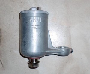
amal7

Float Chamber

This is a bottom feed chamber so the float needle is dropped into place through the fuel inlet union and the float dropped onto it from the other end.

With an original float, it is held onto the needle by a spring clip fixed onto the top of the float so the clip has to be nipped between fingers and the float slid down the needle until it engages with the correct one of the two notches on it.

With a 276 carburetter you use the lower of the notches on the needle and you have to push the needle up at the same time as you slide the float down it until you feel the clip engage the notch.

The modern, plastic, replacement float uses a loose clip, the same part as secures the throttle needle in the throttle slide, to locate the float needle rather than having the clip as part of the float.

Now it’s just fit the float chamber top and tighten the locking screw on it and you then fit the float chamber onto the base of the mixing chamber, using a new fibre washer either side of the banjo, but don’t nip it up tight yet! and the assembled carburetter can be put on the shelf till it has to be fitted.

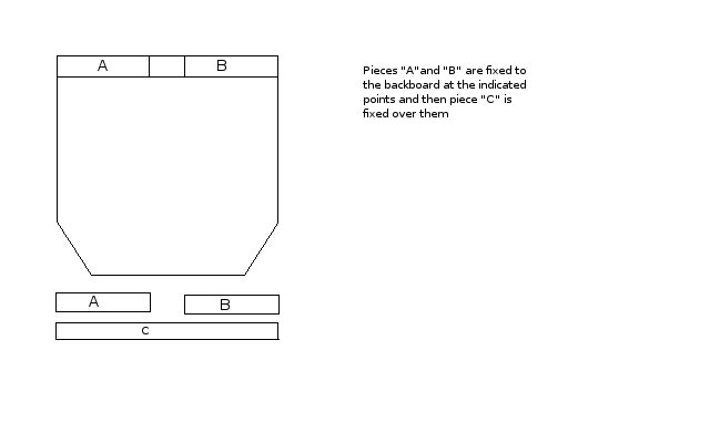
When you come to fit the carburetter to the bike first thing is to attach the throttle and choke cables to the two slides.

The cable inner wires fit through the adjuster screws on the chamber top.

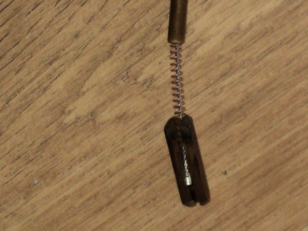
Tthe choke cable then goes through both the upper guide tube and the spring for the choke slide and then, while the spring goes down inside the slide the end of the cable is slid down through the slot in the slide and then the nipple is seated in the bottom of the slide.

Amal8

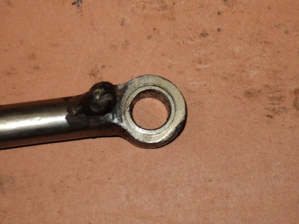
Fitting choke slide cable

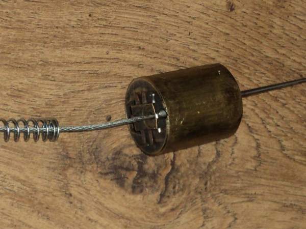
The throttle cable goes through the throttle slide return spring, attaches to the socket in the outer edge of the throttle slide and is retained in place with a split cotter.

Amal9

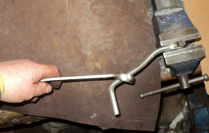
Fitting throttle slide

The two slides can then be slid into place in the mixing chamber, the top fitted in place and the ring nut screwed down.This is made easier if you set the choke slide to the open position and hold the throttle open so their springs are compressed.

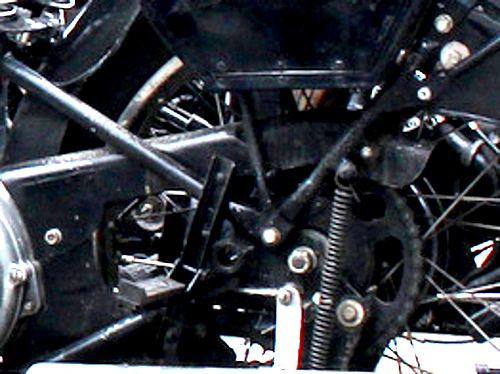
The body is then bolted onto the inlet port adaptor with a heat-insulating washer between it and the inlet stub and the copper fuel feed pipe attached to the base of the float chamber.

NOW you can tighten the bolt attaching the float chamber to the mixing chamber.

Once this is done you can set up the free play in the throtle and choke cables using the adjuster screws on the mixing chamber top.

As the jetting has already been set up to the published figures all that’s left is to set the tick over and the pilot air adjustment, but this has to be done on a hot engine.

The basic settings, with the pilot screw one and a half turns out and throttle stop one turn open, will allow the engine to start and run, if it’s tickover is too fast you can turn back the throttle stop a bit but you now need to go for about a ten mile run to get everything warmed through.

Then, working quickly so the engine does not overheat, it’s just a case of reduce tick-over with the throttle stop until the engine begins to falter, you now adjust air screw till it speeds up, then slow it on the throttle screw again and repeat until it’s as slow as it will go, then screw in the air screw an eighth of a turn.

Check it now picks up cleanly when you add a bit of throttle and that’s the job done.

Pushing on

(This one is out of sequence as I forgot to post it, sorry.                                                                 It should appear between “Sod’s Law Strikes” and “On Tap”.)

Once I had the clutch assembled it needed adjusting and I ran into another snag, there was no free play in the mechanism.

The linkage consists of a lever inside the gearbox outer cover, a short connector piece it bears against, a 1/4 inch ball bearing and the pushrod itself.

It is not possible to mis-assemble at the lever/connector as if you do the outer cover of the gearbox will not go home and omitting the ball would leave too much play so suspicion fell on the pushrod.

Checking the books showed there were two slightly differing lengths available for the pushrod across the period when my bike was built but I found no reference as to when the change was made.

So it was a case of take off the clutch spring plate, remove the pushrod and check which one I had.

On removing the pushrod it was obviously a home made rod and rolling it on the bench showed it was bent so I decided to make up a new one to fit.

To do this I got a length of 1/4inch diameter silver steel rod. This is readily available, I got mine from Cromwell Tools

It comes in a 13 inch length and is diametrically accurate to within 0.00025 inch, not only that but it is easily heat treated to harden the ends.

First thing was to measure the old pushrod to determine its length, as it was very nearly correct in length I cut the silver steel to the same length and made a check assembly of the clutch.

Sure enough there was still no free play so I shortened the new pushrod by gripping it in padded jaws in the vice and filing the end back a bit.

Because it’s much easier to remove material than to add it I only removed a little then tried another check assembly then repeated the operation until I had the play I wanted.

The ends of the pushrod were then polished with a hand held oil-stone and the sharp edges taken off at the same time.

Now to harden the ends. Because of the composition of silver steel all you need to do is heat treat it, there’s no need for Kasenit treatment as it would if I had used bright mild steel to make the pushrod.

First stage was to heat one end until it was bright red-hot, about the colour of a cut carrot, and to hold it at that temperature for a couple of minutes.

The red-hot end was then plunged vertically into water and stirred round vigorously to quench it.

This hardens the heated metal to a “glass-hard” state, one where a file or a hacksaw will “skate” on the surface and will not cut it, downside is that at this state of “temper” the metal is brittle.

So I next “drew the temper down” so it was no longer as brittle but was still a good bearing surface on the ends.

To do this the now discoloured end was cleaned with some fine wet and dry paper and given a polish. The trick now is to apply heat to the rod about an inch in from the end and watch the colour change at the end.

As the metal was heated, at the heated point it turned blue and was kept at this.

Colour could be seen to move from the blue area down the pushrod and at the polished steel end it first showed a light yellow and when it had darkened to a yellow-brown it was again quenched.

This drew down the temper to the level you would use for making a punch which is what I wanted for this job.

If you want more details as to tempering steels a web search will throw up a number of sites such as this one;( be careful, this site is very moreish!).

Having done one end of the pushrod I then hardened the other in the same way and I had my new pushrod ready to fit.

Back Up

When I first made this sidecar I had a seat made for it, this seat is not really satisfactory but when I tried to have one made up properly I was told it could not be done at reasonable price, reason given was “No-one does it like that now-a-days”, which is why I’ve now made up a new one myself.

2 seats

The two seats, commercial one on the left.

As you can see the “professional seat” has been made by simply taking two blocks of foam and putting a cover on them and has a much thicker apron than the one I made, which is copied from an original Steib seat, the “bought in” looks like something you’d find on a bus!. This extra thickness reduced the knee clearance inside the cockpit and also made it a bit more difficult to get into and out  of the sidecar. As the apron lies on top of a set of tension springs set into the cockpit floor it does not need to be as thick as this hence the thinner apron on the genuine Steib seats.

Seat "aprons" compared.

Seat “aprons” compared.

First thing in making up the new seat was sorting out materials.

What’s needed is a new back-board, foam padding and covering materials.

The seat has a wooden back that hooks over a tongue on the top of the rear bulkhead of the cockpit and at the bottom is shaped to fit into the octagonal body.
seat back

This is the tongue the seat locates over

Onto this board is fixed a block of upholstery foam which is covered and held in place with heavy calico and over this goes the reeded top-cover with lower “apron” that goes on top of the support springs.

Under the seat

The springs that support the “apron”

On looking round the ‘net I found “Woolies” from whom I could source the foam and covering materials and I went down to the local DIY shop for some 12mm plywood from which to make the backboard.

I ordered up some 50mm and some 38mm foam along with the red vinyl covering material and calico.

To stitch the covering together I used an old-fashioned “Singer” hand-cranked sewing machine  fitted with a needle intended for sewing leather.

A modern electric machine baulks at sewing the multiple thicknesses of the materials I’m using.

The foam was supplied as a rectangular block and had to be cut to shape, this was easily done using an electric carving knife, bought as a special offer and afterwards donated to the kitchen.

First thing was to make up the backboard

The flat main board has a top “overlap” that is made up from another three pieces of plywood fixed to this board to allow it to locate over the tongue on the seat bulkhead.

Backboard

Backboard

The two pieces “A” and “B” were glued and screwed to the top of the backboard as in the sketch and then the long piece “C” glued and screwed on top of those.

The piece of 50mm foam was cut to fit onto the side of the backboard away from the overlap and then glued onto the board with PVA glue.

The foam was then covered with a piece of the calico which was taken round onto the back of the board and fixed there, PVA glue again and a staple gun used to secure it.

To be continued:-