Category Archives: Panther

Panther motorcycle restoration

BELT UP

Back in the early days of biking (and of cars!) what you bought was the basic machine.

“Luxury” items such as lights were added after-market by the owner to suit their personal preferences and this meant that they came without any  electrics other than a magneto for the ignition.

For lights there was the choice between acetylene gas powered lights and electric ones, gas lights having the advantage of being a complete and separate system whose generator only needed to be kept filled with carbide and water but needed regular cleaning and refilling while an electric systems generator needed to be driven, a gas system was also cheaper than an electric.

A cycle type dynamo driven by one of the wheels was tried but found wanting so it went to being driven from the engine, but it also needed a “power storage unit” that is:- a battery.

Since it was an “add-on” this meant that the generator somehow had to be bolted on somewhere near the engine and then had to be driven from it somehow, even today on a car the alternator still is a “tagged on” part like this even after over 100 years of development!, but modern bikes have moved on from this primitive system.

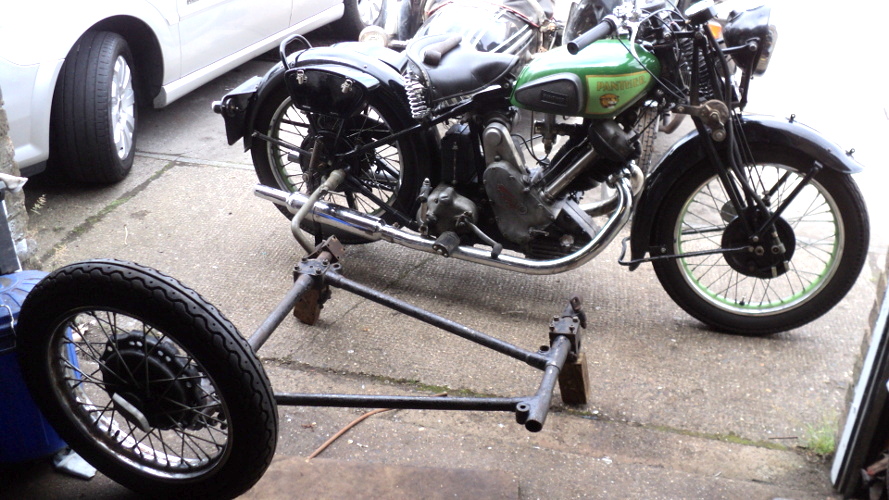
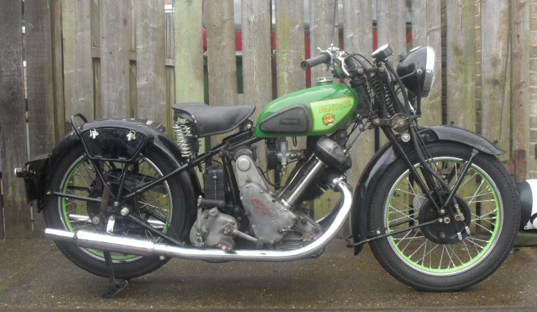
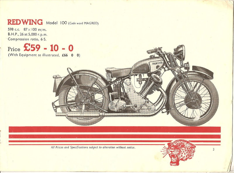
However my Panther is a 1937 machine.

At this time, while bikes no longer came without lights as a standard fitting this was a recent innovation, as a “for instance” my 1929 Triumph was supplied without lights, they were still basicly a “bolt on” accessory.

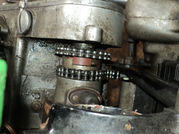
The Panther has a 6 volt 36 watt dynamo bolted to the frame top tube, just in front of the seat tubes, and this is driven from the magneto’s drive coupling by a small duplex chain, this chain having a cast aluminium cover.
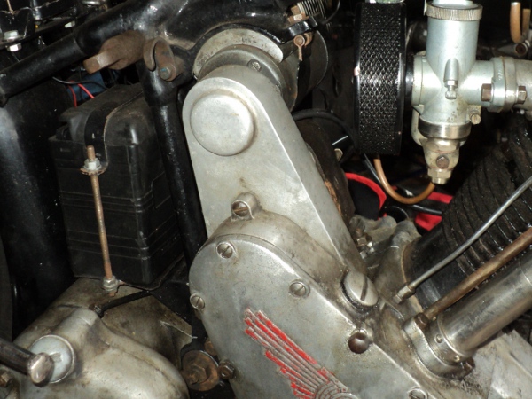
Dynamo

Position of dynamo

This drive is a known weak point on the bike, being prone to wear and possible breakage, and in the event of breakage it can cause damage to the engine housings and stripping of the timing gears in the event that the broken chain jams the magneto drive.
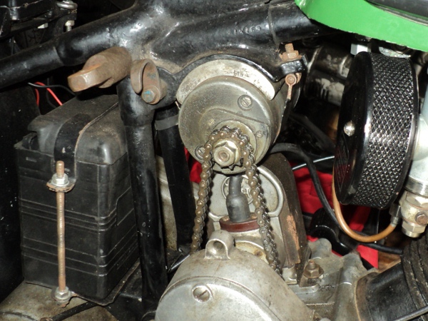
Dynamo drive

Dynamo drive chain

While it was not available back in 1937, there is a safer modern alternative available in the form of a toothed belt drive and I’ve decided to go this route since the dynamo chain on the old girl is showing signs of wear, as are the drive sprockets.

Investigations on the internet soon showed details of what was available in the form of toothed belt pulleys and drive belts as well as sources of supply of these.

On the Panther the drive sprocket has 30 teeth on it while that on the dynamo has 11, giving a 2.7 to 1 “gear up” in the drive, a maximum RPM for the dynamo in the order of around 7,000 RPM and of some 2,500 RPM at 30mph.

Drive Sprocket

Drive sprocket

I have fitted an electronic 12 volt converter onto my bike and since a downside of this is that it has a higher dynamo “cut in” speed than at the original 6 volts I’m going to take advantage of the conversion to uprate the dynamo speed a little and have decided on the use of a 14 tooth pulley on the dynamo and a 44 tooth as a driver.

This will give a dynamo speed of nearly 3000 RPM at 30mph and a maximum of around 8,000 RPM. From the use of these dynamos on other marques of bike I know this is well within the capabilities of the dynamo.

So I ordered up a pair of pulleys and a suitable toothed belt, which arrived two days later.

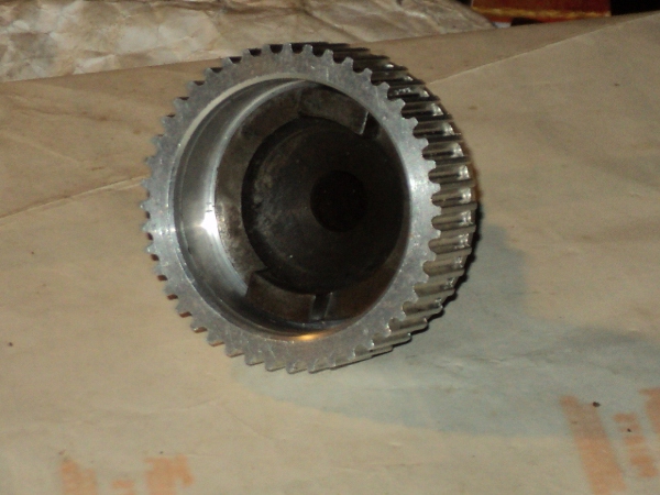
The small pulley turned out to be the neat belt width, there being a pair of cheek flanges to retain the belt in place and it was made from steel while the larger pulley was a wider, aluminium, unit and without the flanges so this will allow for a small measure of misalignment between the pulleys. Both pulleys were supplied with a “pilot bore” in their centres.

First thing was to sort out the drive pulley so as I have a spare drive coupling I decided to use that for the conversion.

This had two chain sprockets, one riveted either side of a flange to give a duplex sprocket. These rivets heads were accordingly ground off using a Dremel tool, the rivets driven out and the sprockets removed.

Once the coupling was offered up to the larger of the pulleys it was found that this flange was slightly smaller in diameter than the pulley and the rivet holes matched nicely with the side of the pulley and so could be used to mount the two together.

The pulley centre was then bored out on the lathe to match the register on the flange that had formerly located the outer sprocket. It was then counter-bored to give a good running clearance for the magneto coupling.

New Pulley

Coupling inside new pulley

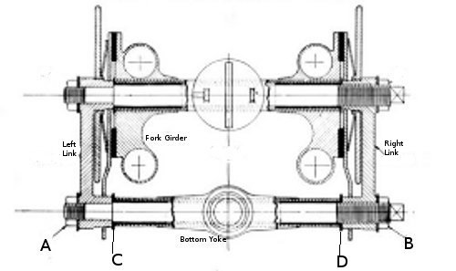
This coupling is a variation on an Oldhams coupling which has the advantage that it can cope with the two sides being a little out of alignment in both plane and angle but it does needs some room to “work” to do this.

Once the pulley had been bored out it was fitted onto the location flange and the position of the rivet holes marked out on it.

The original rivets were 1/8 inch diameter so it was decided to use 3mm Allen cap head screws in their place so the pulley was now drilled and tapped to suit and then secured in place, the screws being secured in place with Loctite.

New Pulley

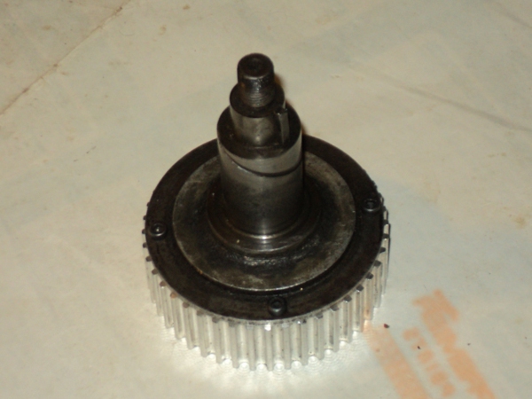
Magneto drive shaft with new pulley fitte

That left the dynamo pulley.

The dynamo has a tapered shaft for this to mount onto. This taper is a standard size across all makes of dynamo, it also is the same as that used on magnetos and is a taper of 1:10 on the diameter.

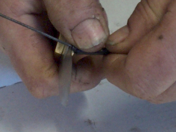
To machine this the top slide on the lathe needs to be set to the correct angle.

To do this I set up a test bar, known to be true, in the lathe and the top slide was adjusted to run true to this.

A 5 inch long ground tool-bit was then put in the tool-holder on the top slide and this was adjusted parallel to the test bar.

The top slide was then reset so one end of the tool-bit was against the bar while a ¼ inch drill was just nipped between its other end and the test bar.

This meant that the top slide was now set to cut a 1:20 taper on the radius, 1:10 on the diameter.

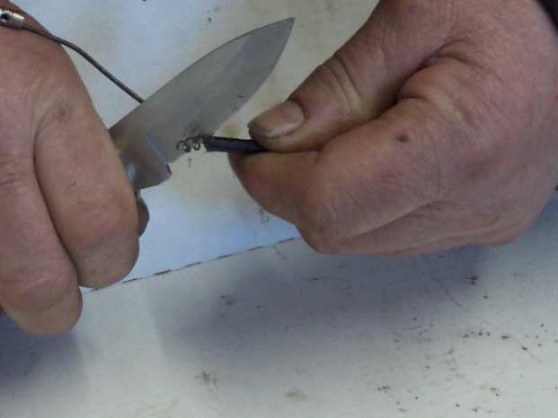
I then chucked up a length of half inch bar, cut a trial taper on it and tried an old chain sprocket on it.

Needless to say it was not quite right but given another couple of tries, making small adjustments to the slide setting each time, and I had a satisfactory result.

All that was left to do was machine the new pulley to suit and all was ready to fit to the bike.


To Be Continued

First Offering

It’s been quite a while since I’ve added anything to this blog, main reasons have been idleness on my part and having been out riding around on the Panther and her stablemates.

I’ve now begun another stage of the project and am prompted to make report.

It’s always been my intention to put a sidecar onto the Panther since doing so will allow me to take my dogs with me on the events that I take her on, as it is, when I go to an event  I have to either use the more modern BMW outfit or leave them behind which is not always convenient.

The sidecar I intend to fit is this Steib

Sidecar 2

As you can see it’s in nice condition

but when I offered it up to the Panther it was immediately obvious that they were not compatible.

Problem was that the Steib was on a chassis dedicated for use with a BMW, the major fittings were in fixed position with no adjustment possible and not only that but they presumed the presence of a front down-tube on the frame.

A problem here straight away because the Panther does not have such a tube!, it uses the engine as a stress bearing member in its place.

Anyway, what it meant was that with the rear fitting coupled in place the front one wanted to be through the timing chest on the engine and undoing the rear fitting and moving the chassis forward showed there was no-where for the front fitting to pick up to when it was moved far enough forwards to allow it to clear the timing chest.

So a change of plans, if the Steib chassis wouldn’t fit then I needed one that would fit, but that would also take the sidecar body.

I began a hunt for a suitable chassis and determined on a Watsonian VG21, a chassis of the same period as the Panther that would also take the Steib body.

Last time I wanted a chassis, everywhere I went I was tripping over VG21’s, but now I wanted one they had become like hens teeth!

I eventually tracked one down and work began.

First thing to do was to convert it to fit on the right hand side of the bike.

Reason for this is that both my other outfits (both BMW) have right-hand sidecars so having another one with a left-hand sidecar is asking for problems.

While doing this I found that the Silentbloc bush that the suspension arm runs on had been replaced with a solid steel bushing and the suspension locked up solid!

After removing this steel bush, and it did not want to be removed!!, I next had to source a replacement Silentbloc but I had a bit of luck here because I found someone who had the correct bush in stock.

So, conversion done and wheel fitted (I’ve not even looked at sorting out the sidecar brake yet!) it was time for the first attempt at offering up the chassis to the bike

At the moment I only have the rear main fitting sorted out so with this loosely fixed onto the sidecar it was connected to the bike and some wood blocks strategically placed.

A bit of shuffling it round and use of a tape measure and there it was in approximate position against the bike.


Sidecar chasssis

First offering up

I was now able to get some other measurements I needed then it was all again dis-assembled.

Main purpose was to check the feasibility of a right hand chair on the old lady, I was fairly sure it would be ok as there is a proper rear mount point for a sidecar at the offside rear , and to get the dimensions for having a swan-neck made up for the job.

This will be a simple piece of pipe-bending, a length of 1¼ inch OD heavy-wall steel tube with a 90 degree bend in the middle, simple to make if you have the facilities, but I don’t so it has to be farmed out.

Getting Tooled Up (3)

I now had the raw mouldings in hand but they were open backed.

To make the backs first the door apertures had to be trimmed to size and shape, a Dremmel tool with a cutting disk proved useful for this.

Next the rear sides of the boxes needed to be trimmed and sanded off level.To do this two sheets of 40 grit sandpaper were clamped onto a piece of MDF board and the boxes rubbed down on these.

Once I had the rear sides sanded down level and to the desired mark but before I moulded on the backs I needed a pair of doors for the boxes since it would be easier to sort out fitting the doors with the backs open.

The doors are a simple flat casting made on a flat board. They are reinforced with a plywood core.

If you remember, the door recesses in the end of the main mould were made by casting over two pieces of 3mm plywood cut to the shape of the door and fixed onto the end-plate of the mould.

These were taken off the end-plate and cleaned of the parting agent. They were then given a good sanding, about  1mm was then sanded off each side to reduce them in size a little and these became the cores for the doors.

A piece of MDF board was given several coats of wax and then a layer of glass cloth laid up on it and a core put in place on top of it.

Door

Door core in place on first sheet

I had got some small cabinet hinges from the local DIY shop and to help secure these hinges to the doors each had one of their tongues enlarged by having a metal semi-circle soldered onto them.

The bottoms of the cores were shaped to accept the hinges, a pair were put in place and another layer of glass cloth laid up over them so there was now a sandwich of glass fibre/ plywood/ glass fibre.

Once the door mouldings had cured out they were trimmed to size and trial fitted in place so the toggle latches that secure them could be fitted, slots being cut to accomodate the hinge “tongues” at the bottom of the door apertures.
With the doors fitted I next had to make the backs.

The inside of the boxes were well cleaned down with acetone and they were then clamped down onto a flat working MDF surface that had been well waxed and then coated with a parting agent.

A bead of plasticene was put round the outside of the moulding/base plate joint to seal it.

The outside of the moulding wasnext covered over in case of accidental splashes of resin onto it and then, working through the door opening, a GRP back was laid up from inside each box.

The problem with these boxes however was that they looked what they are, a GRP moulding and the way round this was simply –  –  –  paint!.

So they were rubbed down and then painted so that they would match the finish on the rest of the bike and would look the part.

Once they were painted then the doors were finally fitted by sliding their hinge plates into the slots cut in the bottoms of the door apertures of the fibre-glass castings, being secured in place with that old faithful, Araldite.

Toolbox

Completed toolbox ready to fit on bike

Rather than mount the boxes with clips to the mudguard stays I made up back-plates from 16 gauge steel sheet. These were fitted onto the stays and the boxes bolted onto these back-plates using spreader plates on the inside of the boxes.

Once the boxes were bolted in place the bike was put on its wheels and a little water was poured inside them to find the low point and a small drainage hole drilled there so that the boxes would not fill up with rain water when out in the “inclement conditions” which so often characterise our riding season.

Finally here’s a lookat how the new boxes appear when fitted to the old lady.

Toolboxes

Toolboxes fitted onto bike

I got all my filler and glassfibre materials from East Coast Fibreglass Supplies in South Shields <http://www.ecfibreglasssupplies.co.uk>.

Their shop is near enough that I just went over there and dealt with them direct but they do mail-order as well and I found them very helpful with advice. The hinges were small cabinet hinges I got from the local DIY shop and the latches came from, of all places, Screwfix!.

Getting Tooled Up (2)

Since the mould was to be made in sections next thing was to provide for this so a pair of plasticene “dams” were placed, one at either end of the top run of the plug, the surface cleaned off with acetone and then this section painted with a parting agent so the moulding would split off the base more readily.

Plug ready to use

Plug ready to use with the Plasticene “dams” visible, the blue tint is the parting agent.


First thing was a layer of gelcoat, this is the consistency of jelly paint and sets to give a smooth gloss surface against the plug or mould so about 75ml was poured into a mixing cup and 2% catalyst added.

To get the amounts right I put the kitchen scales inside a plastic bag to keep them clean and weighed the resin used.

The two components were thoroughly mixed together and the resulting gel brushed onto the prepared section of the plug.

Gelcoat takes around an hour to set so the job was put to one side in the warm and left to set.

While this was going on I prepared for adding the support layers. Since the plug was 100mm wide I cut 4 strips of glass mat, each 100ml wide and long enough to cover the section, I also cut two pieces of thin plywood 20mm wide by 100mm long to reinforce at the joints.

Once the gelcoat had set next thing was adding the first support layer. These layers are of glass mat reinforced resin so as I already had the mat prepared it was now a case of “Mix the resin”.

About 120mls of the laminate resin was poured into a mixing cup and weight checked, 2%of the catalyst was added  and the whole well mixed.

A generous layer of this resin was then brushed over the gelcoat and the first strip of the glass fibre mat laid onto this.

More resin was added to the topside of the mat and worked into the mat so that it was in close contact with the gelcoat, a roller made this job easier and the plywood reinforcing pieces were put in place at the two “dams”.

A second layer of glass fibre was then added over the first and “wetted out” with resin as before and the job put aside to allow the resin to set.

First layer on plug

Plug with first layers of mat added, the plywood end reinforcements can readily be seen

Once it had hardened then the whole thing was repeated to add another two layers of the glass reinforced resin and the job left overnight to setup.

The plasticene dams were then removed and the areas where they had been was cleaned off with white spirit to wash away the plasticene.

Another dam was put halfway along the bottom run of the plug so that the final mould would be in three pieces.

The ends of the first section were tidied up by removing surplus glass matt, the section wiped clean with acetone, coated with parting agent, laid up with glass fibre and left to harden.

Then the last plasticene dam was removed and the whole rigmarole repeated  for the last section, after which the whole moulding was allowed to dry and harden overnight.

Two locating holes were next drilled in each of the section ends, where the dams had been, and then the screws securing the side pieces removed and these were knocked off.

A plastic wedge was used to separate the pieces of the mould and these were cleaned up with acetone and polished.

Now the mould for the door face had to made up.

For this a piece of plywood was cut to fit neatly inside the mould and then another piece cut to the same shape but 12mm smaller all round. This smaller piece was centred onto the first and secured in place.

Door face mould


Mould for door face

A fillet of Plasticene was then put round the join between the pieces and to make it a concave fillet it was smoothed over with the ball end of an old pushrod. This gives a nicely rounded edge to the recess the door will fit into.
This assembly was screwed onto a piece of MDF board and the parts of the main mould then bolted together round the “door” piece.
A Plasticene fillet was now put round between the main mould and the door, again being finished with the pushrod end.

Mould ready to use

Mould ready to use

Procedure to make the toolbox moulding itself was much the same as for making the mould, wipe over with acetone, a coat of parting agent over the inside of the mould followed by a layer of gelcoat.
Once that had set the mould was then layered with glass mat and resin and left to cure.

Toolbox casting in mould

Toolbox casting in mould

The bolts holding the mould together were then removed and the mould peeled off the box moulding, the face piece was removed and I had the raw moulding of the toolbox.

Raw MoultingRaw casting just out of the mould (the white is the plasticine fillets)

To make the other box it was just a case of transfering the smaller part of the end piece from one side to the other of the main piece, re-assembling the mould the other way up and I then had a mirror-imaged pair of toolboxes just needing their door apertures cleaned up and the excess material round the moulding removed.

TO BE

CONTINUED

Getting Tooled Up.

Missing from the bike when I got her were the rear chainguard and the toolboxes.

The chainguard has been replaced with a modified guard from another bike, a Velo, so that just leaves the toolboxes.

There are two of these, one mounted either side of the rear mudguard and they are mirror images of each other, shaped like a truncated triangle but having a curved top to match the curve of the mudguard, as in this catalogue picture.

1937 Catalogue Picture

1937 Catalogue Picture

The possibility of finding a pair of these is so slim as to be discounted so it meantfabricating them, either in metal or in fibre-glass and as by no stretch of the imagination am I a tinsmith there was really only the second option viable.

This meant making up a dummy box or “plug” to make a mould from and as I have an alloy template of the shape and some reasonable photographs that was not too difficult.

To make the plug I cut out a front and a back pieces from 10mm plywood, they were cut as a pair and the alloy template screwed onto them.

DSC01963

Template screwed onto 10mm plywood

They were then attacked with a coping saw

  PIC DSC01964

Rough cut to shape with a coping saw.

to get them near to size and finally sanded to shape.

DSC01965

Sanded to final shape

A set of locating holes were bored through the pair and the screws removed.

The end plates needed to be spaced apart to make the plug so lengths of tightly fitting dowel were pressed into these holes.

3mm plywood was next used to close off the sides between the dowels and then body filler added to get near the required contours

DSC01966

Woodwork completed and adding filler. The screws are to key the filler in place

The filler was added in several layers until it was a little proud of the side pieces and allowed to harden before being sanded down to give the final shape.

DSC01967


Plug being sanded to shape, the locating dowels can readily be seen

With the centre piece of the plug being completed it was treated with wax polish and then the next thing was to fit a pair of side cheeks.

These were cut from a piece of MDF board and their surface well treated with wax polish before they were screwed onto the sides of the centre piece.

DSC01967

Plug core being fitted to cheek


DSC01969

The completed plug


TO BE CONTINUED

Let There Be Light.

Last time I went to go out on the Pussy I found the battery was nearly flat.

Due to the risk of interfering little fingers switching the lights on in the garage I always disconnect the battery when I park her up, there’s a quick-connect there for this very purpose, so I realised something was wrong.

Once she was fired up I switched the lights on and revved her up, sure enough the ammeter showed a steady discharge and the lights did not brighten up, the dynamo wasn’t charging!.

So it was down to the garage today with meter and tools.

Main suspect was the dynamo itself, it being both elderly and a product of the Prince of Darkness.

First thing was to uncouple the drive, this meant removing the dynamo chaincase and then the dynamo itself, not difficult but fiddly, the electrical disconnect was easy, just take out the lock-screw and plate, pull out the  two “plug” connectors and I soon had the dynamo on the bench.

First to be checked were the brushes had they stuck in their holders?, were they contacting the commutator?, what was their insulation like?, how about their connections? All seemed well here.

Next I put a piece of paper between each brush and the commutator and tried the meter across them, maximum ohms as it should be, check each brush to earth, one was virtually nil ohms and the other maximum, again as it should be, removed the pieces of paper so the brushes were in contact with the commutator and measured across the brushes, a low ohms reading so that’s OK, try two or three other positions round the commutator and the readings were the same so that side of the dynamo seemed OK.

This left the field coil so I put the meter across it and found a low ohms reading, as it should be, so I tried the meter across the coil to earth, found the same low reading and promptly thought I’d found the fault in the coil shorting to earth.

I then realised that one end of the coil was MEANT to be connected to earth so I disconnected that end, tried again and got a maximum reading so the coil checked out.

Since the dynamo checked out electrically I next tried a quick and dirty check, if you connect a battery across a dynamo it will run as a motor, this is not an absolute check, since while if it doesn’t motor then it’s definitely  U/S  the fact it will motor is not a guarantee of it being OK, just an indication that it probably is .

To motor a LUCAS dynamo you need to connect the “D” and the  “F” terminals in the dynamo together  and connect them to the live side of your battery, connect the other side of the battery to the dynamo casing and it should spin over and mine did, so, taking the electrical checks along with the dynamo motoring the dynamo seemed OK.

Next to check was the regulator and to access this meant the saddle had to come off.

So it was unbolt the saddle springs, remove the front pivot bolt and lift it away, much easier to say than to do!

The regulator is bolted to the saddle support bracket so that was next and I had the regulator loose in my hand.

The fault was immediately apparent, a broken wire!.

The brown lead to the “A” terminal had broken just where the inner wire leaves the insulation, it was being held in place by the harness but was not making a connection.

The “A” lead is the one taking power from the regulator forward to the ammeter and hence the main switch and from there back to the battery so it’s not surprising the battery was flat.

The connection was soon remade and then everything had to go back together again.

As a point of information, the connections to the regulator are usually in the order “F”  “A”   “D”  “E”, that’s Field, on Panther that’s the green lead, “A” goes to the Ammeter and gets the brown lead, “D” goes to the Dynamo and is the yellow lead and the black Earth lead goes to “E”.

Some of the late pattern post-war regulators had them in the order “D”  “E” “A”  “F” but a quick look at the wire colours tells you, the only ones I’ve seen like this were the late pattern rubber mounted regulators with the crimped on aluminium casing.

Fork It

I’ve now got some 300 miles up on the old girl and it’s time to make the initial running adjustments, a 300 mile service as it were, but I’ll leave the initial oil change till just before I put her away for the winter or 500 miles, whichever comes sooner.

Most of these are obvious ones, valve clearances, chain adjustments, cable free play and such, but one set are not, the front forks.

After the Second War there was an almost universal adoption of the hydraulicly damped telescopic fork for front suspension on bikes.

Previously there had been several options but probably the most common was the “parallel ruler” type or “girder fork”.

In the late 1930’s Panther did not make their own forks but bought them in from “Webb”, probably the best known of the proprietary manufacturers. For the Model 100 they used Webbs “HeavyWeight” fork, similar to that pictured below which shows the fork as intended for use on a Velocette motorcycle. This is taken from the “Webb” catalogue of the time, which I have lifted from the “Velobanjogent” website HERE

Webb Girders

Webb Girder Forks

This pivots on four spindles, two running in the yokes and two in the fork girder, the spindles being joined by pairs of links, the illustration below shows the layout, here in a different fork model and again taken from the same catalogue.

Webb Links Set Up

Webb Links Set Up

What needs to be adjusted is the freeplay of the spindles, if it is too tight the links are pulled tight against the yoke and the fork girder and the fork becomes locked up but if too slack then the girder can move side to side to the detriment of the handling.

As you can see the right link has the spindle threaded into it while the left one is plain and locks up against a shoulder on the spindle, adjustment is by threading the spindle further into or out off the right link.

To gauge the free play there are a pair of knurled washers at “C” and “D”. Adjustment is correct when one of these is held firm by the link but the other can be rotated, that means there is minimal free play in the joint.

When I rebuilt the old lady I had the forks refurbished by Percival and Webb down in Birmingham. However now they have a few miles on them things have settled in and they now need adjustment, a bit of excessive free play having appeared.

To make the adjustment one end of the spindle is squared to take a spanner, however I prefer to use a tap wrench here as I find it gives better control.

Spindle Adjustment

Adjusting top rear spindle

The adjustment technique is not quite as obvious as it seems, first you slack off both the locknuts “A” and “B” and make your adjustment of the spindle.

You the tighten locknut “B” followed by “A” and then you check the play, if it’s right all well and good, if not try again. It’s a bit fiddly but you soon get the feel for it.

If you try to set the play without retightening “B” each time, and then locking it up afterwards you’ll find things set too tight because when you pull up on “B” it moves the link a fraction inwards on the threads by enough to take out the freeplay you have just so carefully set! Experience speaking here!.

Once you have one spindle set then you move onto the next until you have all four set.

Since the spindles are working in plain bushes you need to keep them well lubricated, this means regular greasing with the inevitable result that there is excess grease appearing at the links that you need to clean up, don’t just leave it as there is a friction damper as part of the lower right link and you definitely do not want any grease to find its way in there!.

Back in the day a standard part of the manufacturers tool kit that was supplied with the bike was a small grease gun, about 6 inches long, intended for this very job.

Basket Case

While doing the clutch recork I noticed that the bottom plain plate of the clutch was sitting a bit too deep into the clutch’s outer‭ “‬basket‭”‬,‭ ‬so that the‭  ‬innermost insert plate was having its tongues bottom-out in the basket cut-aways.

This meant that the bottom insert plate was only gripping on one side, also because there was no “sandwich effect” with the insert plate between a pair of plain plates, the grip on the upper side of that plate was impared. This means that the clutch had lost‭ between ‬1/6 and 1/3 of its gripping area.

Bottom Plate

This is the bottom insert plate. This picture is of the upper side and you can see that the inserts have been pressed flush with the plate. There are also scuff marks where the metal of the plate has been rubbing against the next, plain, plate.

It also said that the inner drum needed a thicker distance-piece between it and the clutch‭ be‬aring cheekpiece.

To sort this out I put a steel-rule through the cut-aways‭ ‬in the basket and across the bottom plate,‭ ‬then measured how far that plate was clear of the bottom of the rule.

The inner drum was then removed and the thickness of the existing spacer measured,‭ ‬this dimension was added‭  ‬to the plate clearance and gave the size of spacer required.

All that then needed to be done was chuck up a bit of round bar in the lathe and turn up and part-off a new distance piece of the correct size.

Once this had been fitted,‭ ‬the position of the bottom plate was again checked,‭ ‬and,‭ ‬once I was satisfied then the clutch centre nut was tightened down and locked in place.

However this changed the distance between the clutch operating lever on the gearbox and the clutch backplate enough to take it beyond the available so a new clutch push-rod needed to be made up, longer than the previous by the additional thickness of the spacer.

Now that the clutch has been re-corked I have to expect that the plates will settle in a bit initially,‭ ‬so I’ll have to look to a clutch re-adjustment‭  ‬after a few miles of bedding in and hopefully that will be the clutch set up for the near future‭!‬.

Getting a Grip

Having replaced the clutch springs a few weeks ago I’ve now some more miles up on the old girl and the clutch is not standing up to the strain.

I’ve more or less expected this since these older Panthers have a cork lined clutch and the plates in mine have seen an unknown amount of use.

They are beginning to slip a bit when kicking the bike over from cold and this of course will only get worse, so I’ve got to do something about it.

In among my Panther swag is a bag of the cork inserts.

wornplate + inserts

A worn plate and some new inserts

and I’d just have to fit them the insert plates, The tricky bit is to get them evenly inserted, I can’t just push them in and hope for the best so I had to make up a jig of some sort.

Since the inserts are each 1/4inch thick while the insert plates are 1/16inch thick, this means that the cork will stick through the plate by 3/32inch (the corks are 1/4inch, that’s 4/16inch thick so cork minus plate is 3/16inch, meaning 3/32inch protruding on each side).

What was needed was to arrange a support for the plate such that it was held 3/32inch clear of a flat surface so I could press the cork inserts in against the surface and that would do the trick, but I needed a fairly accurate 3/32 measure for the job.

Simple and cheap to use for this is silver steel rod, it’s easy to get and its diameter is accurate to a quarter thou’ so it was pop down to Cromwell Tools and get some from their stocks for the princely sum of £0.81 for a pair(plus tax!).

Silver steel

The two lengths of silver-steel

On the other hand there are the new inserts, these of course are now bone dry having been “in stock” for years and they’re a bit fragile so they needed to be softened up a bit.

The way to do this is to soak them, and to soak them in boiling water at that, so I popped them in a pan, added water and brought it to the boil. They were then left to stand overnight and next morning they had darkened in colour and were much softer to the touch and more flexible.

Next was to make up the jig.

This doesn’t need to be anything complicated since all it needs to do is support the insert plate 3/32 above a flat surface while the insert is pressed in.

What it’s doing is to support the insert plate on a length of the silver steel rod above the work-top and then arrange another two short lengths of the silver steel, one supporting either side of the aperture I’m working on.

fitting jig

The jig, lengths of silver-steel superglued onto a backboard.

A piece of composite board formed the base and the silver steel was glued onto it with “superglue”.

Worn plate

Worn plate edge on

This picture shows one of the worn insert plates and you can see how thin it has worn.

inserts

New and worn cork inserts

This shows a pair of the cork inserts, a new one at the top and one taken from the plate below it, As you can see it’s worn to less than half the original thickness and shows signs of charring.

Next step was strip out the old inserts and then fit the new cork inserts into the plate to the requisite depth.

Rather than fit an insert at a time in the jig I found it best to fit every other insert and then use the jig to set them to the same depth.

I then turned the clutch plate over and inserted the others from the opposite side and then levelled those ones with the jig.

recorking plate

The plate 3 parts finished

The first plate on the jig, about 3 parts done.

To make sure the insert corks have a level surface either side of the plate was then touched up onto a sheet of emery-paper taped onto the flat surface until all the inserts were faced in.

 
Linishing plate

The recorked plate being finished off on emery paper

That was one plate done and there are three in all, with 30 inserts to fit into on each plate so it’s not a five-minute job!.

Once all three were done then it was just a case of rebuild the clutch and set everything up from scratch, as was done at  the initial build.

Breathing alterations

I’ve now got about 70 miles up on the old lady.

As said earlier she had a Amal Type 276 carburetter fitted rather than the correct Amal Type 89.

Major difference is that the 276 has a smaller bore so the old girl has been undercarburetted.

This model of the carburetter was fitted to the 500cc Panther of this period and I found it was set up as specified for that bike, not only that but it had the same type suffix on the carb body so I suspect that at some time the carb from the other model has been fitted in error.

Having a few miles up now, and on checking the plug finding her running rich even though there is a No.5 slide fitted and the carb set lean, I decided to bite the bullet and get the correct carburetter for her.

Options were to look for a used one or get a modern rebuild.

On checking with Amal themselves I found that the Type 89 was not available but the slightly later Type 289 was.

The difference between them is that the 289 takes its pilot air supply from the main air inlet while the 89 takes it from holes in the side of the body and I decided to opt for the 289.

After a bit of discussion with Amal I ordered a new body less the float chamber, I do after all have a NOS chamber on her now so don’t see the point of getting another one.

The new body cost just over £170 plus post and the inevitable 20% tax .

Two days later a package arrived in the morning post.

In it was a box full of paper shred packing and an “AMAL” box.

Box

Amal Box

Inside that, wrapped in more packing, was a split new Type 289, already jetted and set up for a 1937 Panther M100 with a full “set up and tuning” leaflet plus an envelope containing the throttle slide spring and a new gasket for between the carburetter and its manifold.

Amal 289

The New Carb

So, out to the garage and fit the new carb.

I had two worries here, the free length available on the throttle and choke inner cables.

First tried was the throttle, and it turned out that there was sufficient free length for the slide to “bottom out”, even when turning the handlebar from lock to lock so no problem there.

But when the choke cable was checked the slide was not bottoming, there was insufficient free length so the cable needed to be altered to suit.

The simple way round this is to shorten the casing of the cable, this has the effect of increasing the free length of the inner cable which is what we want and all that’s needed is an extra 1/4 inch of that free length.

This is one of those fiddly jobs that isn’t often done but if you do know how to do it, it can save you a lot of trouble.

The obvious way is to unsolder one nipple, cut the casing back and then resolder the nipple but this is easier said than done because often solder will not “bite” onto a used cable.

It is however possible to just trim back the outer casing itself without removing the nipple.

To do this you first slide the ferrule back of the end off the casing, up to the nipple and out of the way, this is probably the most difficult part of the process depending on how the ferrule is fixed in place, but using a sharp knife to knick round the casing at the ferrule’s base will normally do the trick.

You can then “winkle” the bit of loose casing cover out of the ferrule and the outer cover needs to be cut back to expose the metal coils anyway.

Then, using your knife press the edge of the blade between the end coils of the casing and then twist the blade to lever them a little way apart.

Step1

Opening End Coil of Casing

You can then turn the blade so as to take the free end of the coil over the inner wire and the casing can then be unwound away from the inner wire for a few turns.

Step 2

Unwinding Casing

Once you have sufficient unwound then just nip off the unwound coils with a pair of cutters.

Step 3

Nipping Off Excess Coils

There will be a sharp “rag end” of the casing left projecting, this can be dressed off with a file or careful use  of a “Dremel” tool and all that is left to do is slide the ferrule back into place and refit the cable.

I’ve found this trick can be useful at the roadside once when I altered a clutch cable from one make of bike to fit another when its cable broke, meant the bike could complete the event and did not need to be “trailered home”.